6-p1125-1147-izn10_en 15 / 29
10秒後にBOOKのページに移動します
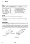
. Resin part ( shaded) 1. Ground the tap for ground wiring or metal ( shaded) parts around the external face of the ionizer with a resistance of 100 Ω or less. If grounding is not provided or is incomplete, the ionizer will not be able to achieve its specified static neutralization performance. Also, the maintenance signal will be generated. 2. If the product is used under the conditions that the pressure around the electrode needle becomes 0.1 MPa or more depending on the piping conditions stated in Note 1) on page 1129, avoid to mount the grounded base or workpiece on the resin part ( shaded) at locations marked with an asterisk shown in the Fig. below. If the grounded base or workpiece is mounted on the resin part ( shaded) under these operating conditions, the ozone concentration around the high-voltage generation substrate inside the ionizer chassis increases, causing the substrate to break. For details about the dimensions of the resin part ( shaded), refer to the dimensions on page 1140. Metal ( shaded) part Wiring Provide Grounding. . Input signal NPN: The signal is turned on when the power supply GND is connected, and turned off when disconnected. PNP: The signal is turned on when the power supply 24 V is connected, and turned off when disconnected. . Output signal NPN: The signal is turned on when the output transistor is energized (by the power supply GND inside the ionizer), and turned off when de-energized. PNP: The signal is turned on when the output transistor is energized (by the 24 V power supply inside the ionizer), and turned off when de-energized. No. Cable color Description I/O Wiring requirement Note) I/O Specifications 1 2 3 4 Brown Blue Orange Pink Power supply +24 V Power supply GND Discharge stop signal Reset signal . . Input Input . . Input Input . . When the signal is turned off, discharge stops. 5 6 7 8 9 White Purple Yellow Gray Light blue Discharge signal Error signal Maintenance signal External switch signal 1 External switch signal 2 Output Output Output Input Input Output Output Output Input Input The signal stays on during discharge The signal is turned off when an error occurs The signal is turned on when maintenance is due. When the signal is turned on, discharge stops. When the signal is turned on, discharge stops. When the signal is turned on and then off, the error signal is reset. When the signal is turned off, normal operation continues. Note) Wiring requirement : Minimum wiring requirement for ionizer operation. Tap for ground wiring Metal ( shaded) part 1138 Series IZN10 a