In![]() struction for CAD Electronic Catalog << Return to CAD System
struction for CAD Electronic Catalog << Return to CAD System
Glossary
|
Q1. Information about crossed-out
data in
the cylinder stroke table
<< Return to CAD System <Return to Explanation of the screens
Glossary (New terms
are constantly added and the glossary is constantly updated.)
Terms
(Alphabetical order)
|
Explanation
|
|
DATE |
The date when the
file was created (update date in the case of design change). |
|
DOS |
DMNDOS data that
can be outputted to M/CADAM directly. |
|
Coordinate origin
of DOS data |
For DOS data, the lower
right corner is the coordinate origin (0, 0). |
|
Coordinate origin
of DXF data |
For DXF data, the
lower left corner is the coordinate origin (0, 0). |
|
MC |
Indicates the
position of the magnet center (maximum sensitivity) of a cylinder body. When an
auto switch is attached to the cylinder, attach it in the MC position of the
cylinder based on the PIVOT point of the auto switch. |
|
PIVOT |
This is the
reference point for combining child drawings. (e.g.
It is used to combine #1 and #2.) |
|
POINT |
When valves that
cannot be indicated by one PIVOT are pasted to the manifold, the term “POINT”
is given based on the number of stations. |
|
SL |
The SL (stretch
line) is used to change the stroke of the cylinder. For data with a stretch line, there is an
overall length table with each stroke; thus, extend the overall length and
the stroke based on the stretch line. When child drawings
are in blocks (grouped), they must be decomposed (ungrouped). |
|
TITLE |
In most cases, the
product series name (or the product name) is given. |
<< Return to CAD System <Return to Explanation of the screens
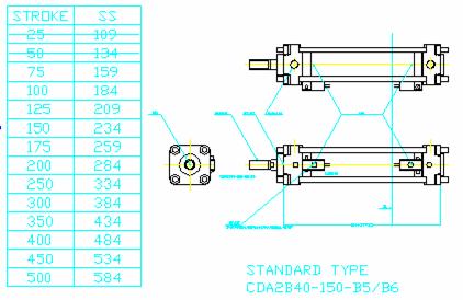
Q1. Information about crossed-out data in the cylinder stroke table
A1.
The crossed-out data in the cylinder
stroke table indicate that the CAD data of those dimensional combinations
cannot be created. (This is because the 2 auto switches will interfere with
each other.)
A product (product part number) based on the crossed-out data can
be made available if the mounting position of the auto switches is changed to
avoid auto-switch interference.
The following drawings show
what happens when the stroke is shortened without moving the position of the
auto switches.
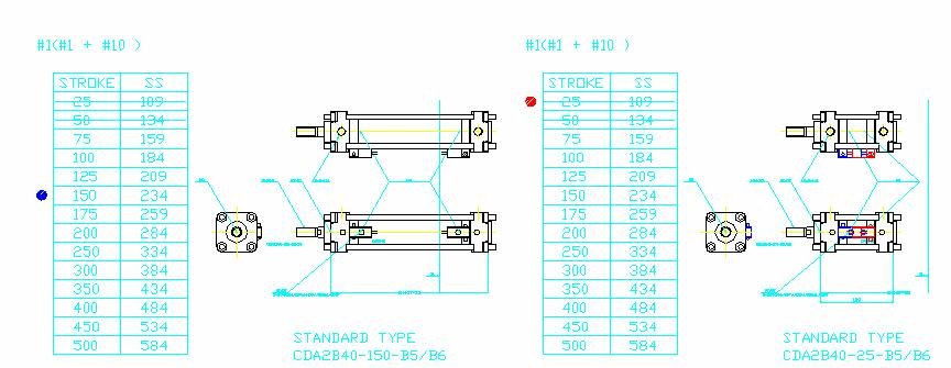
Fig. 1 Master
drawing
Fig. 2 Drawing with modified stroke (ST=25mm)
(The
auto switches are colored in blue and red to express interference.)
<< Return to CAD System <Return to Explanation of the screens
©2005 SMC
Corporation all rights reserved.