smc-atex-en-web丂丂丂6 / 119
10昩屻偵BOOK偺儁乕僕偵堏摦偟傑偡
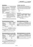
Series Coil temperature rise Barrier input voltage (non hazardous area) Coil rated voltage (hazardous area) Intrinsically safe Gas group .10 to 45亱C (No freezing) .10 to 50亱C (No freezing) 40亱C less (at rated) 24 VDC (system rated voltage) at 1.1 W 12 VDC at 0.52 W ia IIC IP30 (LL type : IP40) IP65 52-SY5000 52-SY7000 52-SY9000 Temperature class T6 Temperature class T4, T5 L type TT type Plug connector type Cable type Response time Type of actuation 2-position single 2-position double 3-position 52-SY5000 26 or less 22 or less 38 or less 52-SY7000 38 or less 30 or less 56 or less 52-SY9000 50 or less 50 or less 70 or less Response time (ms) (0.5 MPa) Manifold Specifications for 20 Type Model Applicable valve Manifold style 1 (SUP) / 3/5 (EXH) Valve stations 4/2 (A/B) Location Port size Manifold base weight W (g) n: Station Single base / B mounting Common SUP / Common EXH 2 to 20 (1) Valve 1/4 SS5Y5-20 52-SY5瓠20 SS5Y7-20 52-SY7瓠20 1,3,5 (P,EA,EB) Port 4,2 (A,B) Port 1/8 C4 (One-touch fitting for o4) C6 (One-touch fitting for o6) C8 (One-touch fitting for o8) 1/4 C8 (One-touch fitting for o8) C10 (One-touch fitting for o10) W = 36n + 6 W = 43n + 64 Manifold Specifications for 20 Type Model SS5Y5-20 SS5Y7-20 Port size Flow characteristics 1,5,3 1 饟 4/2 (P 饟 A/B) 4/2 饟 5/3 (A/B 饟 EA/EB) (P,EA,EB) 1/4 1/4 4,2 (A,B) C8 C10 1.90 3.60 b 0.28 0.93 Cv 0.48 3.60 2.20 0.93 b 0.20 0.27 Cv 0.53 0.88 Manifold Specifications for 41 and 42 Type Model Applicable valve Manifold style 1 (SUP) / 3/5 (EXH) Valve stations 4/2 (A/B) Porting spec. Port size Manifold base weight W (g) n: Station SS5Y5-41 SS5Y5-42 SS5Y7-42 52-SY7瓠40 Location Direction 1,3,5 (P,EA,EB) Port 4,2 (A,B) Port 1/4 1/4 1/8 C6 (One-touch fitting for o6) C8 (One-touch fitting for o8) 1/4 C6 (One-touch fitting for o6) C8 (One-touch fitting for o8) 1/4 C10 (One-touch fitting for o10) W = 61n + 101 W = 79n + 127 W = 100n + 151 Manifold Specifications for 41 and 42 Type Model SS5Y5-41 SS5Y5-42 SS5Y7-42 Port size Flow characteristics 1,5,3 1 饟 4/2 (P 饟 A/B) 4/2 饟 5/3 (A/B 饟 EA/EB) (P,EA,EB) 1/4 1/4 1/4 4,2 (A,B) C8 C8 C10 1.80 1.90 3.00 b 0.23 0.20 0.25 Cv 0.44 0.46 0.75 c[dm3/(s丒bar)] c[dm3/(s丒bar)] c[dm3/(s丒bar)] c[dm3/(s丒bar)] 1.90 1.90 3.00 b 0.16 0.12 0.12 Cv 0.45 0.43 0.66 52-SY5瓠40 Standard SY manifolds Types 20, 41, 42 are used for 52-SY valves. Ambient and fluid temperature Protection rating Note) Impact resistance: No malfunction resulted from the impact test using a drop impact tester. The test were performed one time each in the axial and right angle directions of the main valve and armature, in both energized and de-energized states (Valve in the initial stage). Vibration resistance: No malfunction occurred in a one-sweep test between 8.3 and 2000Hz. The test was performed for both energized and de-energized states in the axial and right angle directions of the main valve and armature (valve in the initial stage). Note 1) For more than 10 stations (more than 5 stations in case of SS5Y7), supply pressure to P port on both sides and exhaust from EA/EB port on both side. Note 2) 52-SY9瓠20 valve are not available with manifold as standard. Note 1) For more than 10 stations (more than 5 stations in case of SS5Y7), supply pressure to P port on both sides and exhaust from EA/EB port on both side. Note 2) 52-SY9瓠40 valve are not available with manifold as standard. Note 3) 52-SY series are not available with resin type manifold (45 type). Single base / B mounting Common SUP / Common EXH 2 to 20 (1) Base Side Safety Instructions Note 1) According to dynamic performance test JIS B8375-1981. Note 2) Response time when barriers were combined with a valve. Note 3) System A: Valve + Z728.H B: Valve + MTL728P+ F: Valve + KFD0-SD2-Ex1.1065 1) This product is not suitable for Zone 0. The suitable zones are Zones 1 and 2. 2) SMC-TAS and TAV Series, antistatic tubing, are available if required. 3) The solenoid valve has polarity. Confirm the correct polarity by observing the color of the lead aires. if the polarity is reversed, the barrier may be damaged. 4) Confirm that the solenoid input voltage at the lead wires is 10.8 VDC (min). 5) This product must be connected to an appropriate barrier (ATEX compliant product), or a certified intrinsically safe circuit, with the following maximum values. Ui = 28 V li = 225 mA (resistively limited) Pi = 1 W Ci = 0 nF Li = 0 mH Note) Values for 5 stations manifold with a 2 position single type valve. Note) Values for 5 stations manifold with a 2 position single type valve. Series 52-SY ATEX Compliant 5 Port Solenoid Valve Specifications 4 B