p-e11-7-25a 17 / 173
10秒後にBOOKのページに移動します
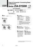
How to Order Manifold 25A SS5Y 5 12 F 1 05 U 5 SY5000 q w e r t y u q Series F: D-sub connector (25 pins) w Connector type 1: Upward 2: Lateral e Connector entry direction r Valve stations Nil S Internal pilot Internal pilot,Built-in silencer . For built-in silencer type, P and E ports are available on U and D sides. 3/5(E) port is plugged. The silencer exhaust port is located on the opposite side of P, E port entry. (Example: When the P, E port entry is D side, the silencer exhaust port is U side.) y SUP/EXH block assembly Nil D D0 D3 D24 Direct mounting DIN rail mounting (With DIN rail) DIN rail mounting (Without DIN rail) For 3 stations For 24 stations u Mounting Specify a longer rail than the standard length. U Note) D Note) B U side (2 to 10 stations) D side (2 to 10 stations) Both sides (2 to 24 stations) t P, E port entry Note) y For type “S”, supply/exhaust block assembly with built-in silencer, choose “U” or “D” for P port entry. Symbol 02 12 02 24 Stations Note 2 stations 12 stations 2 stations 24 stations Double wiring Note 1) Specified layout Note 2) (Available up to 24 solenoids) Note 1) Double wiring: 2-position single, double, 3-position and 4-position valves can be used on all manifold stations. Use of a 2-position single solenoid will result in an unused control signal. If this is not desired, order with a specified layout. Note 2) Specified layout: Indicate the wiring specifications on the manifold specification sheet. (Note that 2-position double, 3-position and 4- position valves cannot be used where single wiring has been specified.) Note 3) This also includes the number of blanking plate assembly. Series 25A-SY5000 RoHS Series compatible with secondary batteries Plug-in Connector Connecting Base Type 12 Top Ported D-sub Connector . Specifications and dimensions for the 25A-series are the same as standard products. F: D-sub connector (25 pins) FREE LOCK LOCK FREE FREE LOCK 15