p-e11-7-25a 150 / 173
10秒後にBOOKのページに移動します
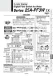
. To use in combination with remote monitor (PF3W3 series), select analog output of 1 to 5 V of flow rate (output symbol “-1” or “-1T”). Series 25A-PF3W PF3W7 04 03 AT M PF3W5 04 03 1T 03 04 06 10 僳 . . . 僳 僳 . . . 僳 僳 . . . 僳 僳 3/8 1/2 3/4 1/1 25A 25A 僳 僳 僳 僳 僳 僳 僳 . 04 20 40 11 How to Order 3-color display Digital Flow Switch for Water Output specification/Temperature sensor Remote sensor unit . Under the New Measurement Law, units other than SI (symbol: “Nil”) cannot be used in Japan. Note) G: Made to Order Reference: 1 [L/min] 0.2642 [gal/min] 1 [gal/min] 3.785 [L/min] °F = 9/5°C + 32 Remote sensor unit/Unit printed on label Symbol OUT1 Flow rate 12 1T . . Analog 1 to 5 V With temperature sensor None Analog 1 to 5 V Analog 4 to 20 mA Analog 1 to 5 V Temperature sensor OUT2 Temperature Integrated display Remote sensor unit Series compatible with secondary batteries Thread type Rc NPT G Nil NF Port size Symbol Port size Rated flow range 04 20 40 11 100 L/min type is not available with flow adjustment valve. None Yes Nil S Flow adjustment valve Symbol With/without flow Rated flow rate adjustment valve Rated flow range (Flow range) Type Remote sensor unit Integrated display 5 7 Bracket (Option) None Bracket Nil R Calibration certificate (Only flow sensor) None With calibration certificate Nil A Symbol Instantaneous Temperature flow rate M G F J Accumulated flow °C °C °F °F L/min gal/min gal/min L/min L gal gal L . Under the New Measurement Law, units other than SI (symbol: “M”) cannot be used in Japan. Note) “G”, “F”, “J”: Made to Order Reference: 1 [L/min] 0.2642 [gal/min] 1 [gal/min] 3.785 [L/min] °F = 9/5°C + 32 Lead wire (Option) With lead wire with M8 connector (3 m) Nil N Without lead wire with M8 connector . Specifications and dimensions for the 25A-series are the same as standard products. . Specifications and dimensions for the 25A-series are the same as standard products. Options/Part No. When optional parts are required separately, use the following part numbers to place an order. Part no Qty. 1 1 1 1 Description Note 25A-ZS-40-K 25A-ZS-40-L 25A-ZS-40-M 25A-ZS-40-A For PF3W704/720/504/520 For PF3W740/540 For PF3W711/511 Bracket Note) Lead wire with M8 connector Note) For units with flow adjustment valve, 2 brackets are required. With 4 tapping screws (3 x 8) With 4 tapping screws (3 x 8) With 4 tapping screws (4 x 10) Lead wire length (3 m) Output specification/ Temperature sensor Symbol OUT1 Flow rate Flow rate Temperature . . . . . . . . NPN PNP Analog 1 to 5 V Analog 4 to 20 mA Analog 1 to 5 V Analog 4 to 20 mA A B C D E F G H AT BT CT DT ET FT NPN PNP Analog 1 to 5 V Analog 4 to 20 mA Analog 1 to 5 V Analog 4 to 20 mA External input Note 1) External input Note 1) (NPN) (PNP) (Analog 1 to 5 V) (Analog 4 to 20 mA) (Analog 1 to 5 V) (Analog 4 to 20 mA) NPN PNP NPN NPN PNP PNP NPN PNP NPN PNP NPN NPN PNP PNP Note 1) External input: The accumulated value, peak value, and bottom value can be reset. Note 2) For units with temperature sensor, OUT2 can be set as either temperature output or flow rate output. Setting when shipped is for temperature output. OUT2 Temperature sensor None With temperature sensor Note 2) Note 2) Note 2) Note 2) Note 2) Note 2) Integrated display Integrated display/Unit specification 0.5 to 4 L/min 2 to 16 L/min 5 to 40 L/min 10 to 100 L/min 04 20 40 11 Symbol Rated flow range . The certificate is written in both English and Japanese. Integrated display type with temperature sensor can only display flow rate. Symbol Instantaneous Temperature flow rate °C °C/°F Nil G. L/min L/min (gal/min) RoHS 148 Air Grippers Air Cylinders Directional Control Valves Related Products Rotary Actuators Vacuum Equipment Air Preparation Equipment Air Filters/Pressure Control Equipment Fittings/Flow Control Equipment Detection Switches Fluid Control Equipment Electric Actuators Auto Switches Clean Air Filters