p-e11-7-25aü@ü@ü@118 / 173
10òbîÒé╔BOOKé╠âyü[âWé╔ê┌ô«éÁé▄éÀ
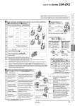
Note 10) Solenoid valve with light/surge voltage suppressor Note 11) Standard lead wire length for solenoid valve is 300 mm. Note 12) For lead wire lengths other than standard, select ügL1 or L3üh, and order the connector assembly desired. (Refer to the table on the right.) Note 13) Standard lead wire length for pressure sensor is 3 m. Standard lead wire length with connector for vacuum pressure switch and the lead wire length for switch with energy saving function is 2 m. Note 14) Select ügL, L1, Yüh when the pressure sensor (P, T) is selected for t Pressure sensor/Digital pressure switch for vacuum specifications. Since only grommet type is available for the pressure sensor, sensor without lead wire cannot be selected. Note 15) Select when no vacuum pressure switch, pressure sensor, or vacuum pressure switch with connector without lead wire is used. y Supply valve/Release valve/Digital pressure switch for vacuum connector specifications Connector type Lead wire with connector L-type plug connector À Note 11) Â Note 12) À Note 11) Â Note 12) À Note 14) À Note 14) Â Note 15) Â Note 15) À Note 14) Â With lead wire for switch with energy saving function Non-valve (without supply/release valve) When ügNüh is selected for e When ügNüh is selected for both e and t (without supply/release valve, without switch, pressure sensor) Symbol L L1 L2 L3 W N Y Y1 i Optional specifications/Functions/Applications Note 17) Type Function/Application Without option . Symbol Nil With one bracket for mounting a single unit (Mounting screw is attached.) With individual release pressure supply (PD) port type Note 18) Vacuum break flow adjustment needle Round lock nut type Vacuum break flow adjustment needle Screwdriver operation type B Note 16) Supply port size of single unit: o6 Type Port size Metric size o6 One-touch fitting o8 One-touch fitting Symbol 06 08 eFor supply valve/release valve Note 10) tLead wire with connector for pressure switch/ sensor Note 13) üE Use when a single unit is mounted to the floor in an upright position is requested. (The part number for ordering only a bracket is ZK2-BK1-A. Bolt nuts are included.) üE Use when supply pressure for vacuum release which pressure is different from the ejector supply pressure is requested. üE Thicker than standard hexagon type. More suitable for hand tightening. üE Round lock nut improves operability when port exhaust type is used. üE Slotted type improves fine adjustment performance when port exhaust type is used. u Vacuum (V) port Note 16) !PV: Air pressure supply port/Port for vacuum source (Vacuum pump) !PS: Pilot pressure supply port !PD: Individual release pressure supply port !V: Vacuum port !EXH: Exhaust port !PE: Pilot pressure exhaust port Note) Refer to the WEB catalog or the Best Pneumatics No. 4 when mounting single unit to DIN rail. D J K With exhaust interference prevention valve Note 19), 20), 21) üE When ejectors are operated individually, exhausted air may flow backward from the V port of ejectors that are OFF. Exhaust interference prevention valve prevents back flow. W Note 17) When more than one option is selected, list the option symbols in an alphabetical order. Example) -BJ Note 18) Use One-touch fittings or barb fittings with O.D. o8 or less for piping. (Recommended fitting: KQ2S23-M3G) Note 19) To prevent backflow of the exhaust air, not for holding vacuum. This option does not completely stop the backflow of the exhaust air. Select port exhaust type depending on purpose. Note 20) When ügJüh is selected for e Combination of supply valve and release valve and ügWüh (exhaust interference prevention valve type) is selected for i Optional specifications/Functions/Applications, install a release valve or vacuum breaker. Note 21) When ügKüh, ügQüh, ügRüh, or ügSüh is selected for t Pressure sensor/Digital pressure switch for vacuum specifications, the exhaust interference prevention valve is provided. So, it is not necessary to select ügWüh. Single Unit and Options Note 22) Note 22) When ügJ or Nüh is selected for e Combination of Supply Valve and Release Valve, ügD, J or Küh cannot be selected for i Optional Specifications/Functions/Applications. For options not in the table, please contact SMC. ù ù B ù ù D ù ù J ù ù K ZK2 A B 5üE6üE0 P to N 06 üE 08 KüEJüERüEN 07üE 10üE 12üE 15 i q w e r t y u L to N . Specifications and dimensions for the 25A-series are the same as standard products. Connector assembly ZK2 LV A W S Valve type K/R (With supply valve and release valve) Valve type J (Supply valve only) Applicable valve type Lead wire length Nil 6 10 20 30 300 mm 600 mm 1000 mm 2000 mm 3000 mm W For single For double Red White Black Red Black V Bracket Vacuum break flow adjustment needle Vacuum break flow adjustment needle PD port Exhaust interference prevention valve 116 Vacuum Unit Series 25A-ZK2 Air Grippers Air Cylinders Directional Control Valves Related Products Rotary Actuators Vacuum Equipment Air Preparation Equipment Air Filters/Pressure Control Equipment Fittings/Flow Control Equipment Detection Switches Fluid Control Equipment Electric Actuators Auto Switches Clean Air Filters