m-03-3c-seihin_en 27 / 77
10秒後にBOOKのページに移動します
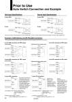
Prior to Use Auto Switch Connection and Example Relay Relay Input COM COM Input COM Input COM Input 2-wire AND connection 2-wire OR connection 3-wire OR connection for PNP output (Using relays) (Performed with auto switches only) 3-wire AND connection for PNP output 3-wire OR connection for NPN output (Using relays) (Performed with auto switches only) 3-wire AND connection for NPN output (PLC internal circuit) (PLC internal circuit) (PLC internal circuit) (PLC internal circuit) 2-wire 3-wire, PNP 2-wire 3-wire, NPN Load Load Load Load Load Load Load Load Blue Black Brown Auto switch 2 Blue Black Brown Auto switch 1 Blue Black Brown Auto switch 2 Blue Black Brown Auto switch 1 Blue Black Brown Auto switch 2 Blue Black Brown Auto switch 1 Blue Black Brown Auto switch 2 Blue Black Brown Auto switch 1 Blue Brown Auto switch 2 Blue Brown Auto switch 1 Blue Black Brown Auto switch 2 Blue Black Brown Auto switch 1 Blue Brown Auto switch 2 Blue Brown Auto switch 1 Blue Black Brown Auto switch 2 Blue Black Brown Auto switch 1 Blue Brown Blue Brown Blue Black Brown Blue Black Brown Auto switch Auto switch Auto switch Auto switch Example of AND (Series) and OR (Parallel) Connection Sink Input Specifications Source Input Specifications Load voltage at ON = Power supply voltage . Residual voltage x 2 pcs. = 24 V . 4 V x 2 pcs. = 16 V Example: Power supply is 24 VDC Internal voltage drop in auto switch is 4 V. Load voltage at OFF = Leakage current x 2 pcs. x Load impedance = 1 mA x 2 pcs. x 3 kΩ = 6 V Example: Load impedance is 3 kΩ. Leakage current from auto switch is 1 mA. (Solid state) (Reed) When two auto switches are connected in series, a load may malfunction because the load voltage will decline when in the ON state. The indicator lights will light up when both of the auto switches are in the ON state. Auto switches with load voltage less than 20V cannot be used. When two auto switches are connected in parallel, malfunction may occur because the load voltage will increase when in the OFF state. Because there is no current leakage, the load voltage will not increase when turned OFF. However, depending on the number of auto switches in the ON state, the indicator lights may sometimes grow dim or not light up, due to the dispersion and reduction of the current flowing to the auto switches. Connect according to the applicable PLC input specifications, as the connection method will vary depending on the PLC input specifications. . When using solid state auto switches, ensure the application is set up so the signals for the first 50 ms are invalid. 22