c-e08-6a-niji 51 / 88
10秒後にBOOKのページに移動します
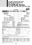
How to Order 40 30 M9BWL With auto switch (Built-in magnet) CDLQ B Cylinder stroke (mm) With auto switch D F Auto switch *For the applicable auto switch model, refer to the table below. Nil Without auto switch Locking direction F B Extension locking Retraction locking Action D Double acting Bore size 20 25 32 40 50 63 80 100 20 mm 25 mm 32 mm 40 mm 50 mm 63 mm 80 mm 100 mm Body option Nil C M CM Standard (Rod end female thread) With rubber bumper Rod end male thread With rubber bumper, Rod end male thread Mounting style o20, o25 o32 to o100 Built-in Magnet Cylinder Model Number of auto switches Nil S n 2 pcs. 1 pc. “n” pcs. 90 Series compatible with secondary batteries 90 91 Material restriction With lub-retainer Compact Cylinder with Lock Double Acting, Single Rod o20, o25, o32, o40, o50, o63, o80, o100 CDLQ Series 90- 91- 90- 91- 20, 25 32, 40, 50, 63, 80, 100 5, 10, 15, 20, 25, 30, 35, 40, 45, 50 10, 15, 20, 25, 30, 35, 40, 45, 50, 75, 100 Mounting Bracket Part No. Bore size (mm) Foot (1) Flange 20 25 32 40 91-CLQ-L020 91-CLQ-L025 91-CLQ-L032 91-CLQ-L040 91-CLQ-F020 91-CLQ-F025 91-CLQ-F032 91-CLQ-F040 91-CLQ-D020 91-CLQ-D025 91-CLQ-D032 91-CLQ-D040 50 63 80 100 91-CLQ-L050 91-CLQ-L063 91-CLQ-L080 91-CLQ-L100 91-CLQ-F050 91-CLQ-F063 91-CLQ-F080 91-CLQ-F100 91-CLQ-D050 91-CLQ-D063 91-CLQ-D080 91-CLQ-D100 Double clevis (3) Bore size (mm) Foot (1) Flange Double clevis (3) Note1) When ordering foot bracket, order 2 pieces per cylinder. Note2) Parts belonging to each bracket are as follows. Foot, Flange: Body mounting screws, Double clevis: Clevis pin, type C retaining ring for shaft, Body mounting screws, Flat washer. Note3) Clevis pin and retaining ring are included with the double clevis style. Applicable Auto Switch/Refer to pages 62 to 65 for detailed specifications of auto switches. M9BW A90 *Mounting bracket is shipped together, (but not assembled). Through-hole/ Both ends tapped common (Standard) Foot style Rod side flange style Head side flange style Double clevis style B L F G D Through-hole (Standard) Both ends tapped style Foot style Rod side flange style Head side flange style Double clevis style B A L F G D Bore size (mm) Standard stroke (mm) If a built-in magnet cylinder without an auto switch is required, there is no need to enter the symbol for the auto switch. (Example) CDLQL32-30D-B M9BWV Perpendicular In-line Type Special function Electrical entry Wiring (Output) Load voltage Auto switch model Lead wire length (m) DC AC Applicable load Pre-wired connector Diagnostic indication (2-color indication) Grommet Yes No 2-wire 100 V or less 24 V 12 V Relay, PLC 3(L) SDPC Indicator light Reed switch Solid state switch . IC circuit . . . . *Specifications and dimensions for the 90-series are the same as standard products. Specifications for the 91-series are the same as standard products. *Additional symbols for auto switch: Lead wire length 3 m・・・・・・・・・・・・・・・・・L Example: M9BWL With pre-wired connector・・・・・・・・・・SDPC M9BWSDPC *Order part numbers for auto switches alone are D-M9BW(V)L-900, D-M9BW(V)SDPC-900 and D-A90L-900. *When mounting the D-M9BW(V)L-900, M9BW(V)SDPC-900, or A90L-900 on cylinders with o32 to o50 other than on the port face, order the auto switch mounting brackets separately. Refer to page 66 for details. *When using mounting brackets (foot, head side flange, or double clevis), an auto switch may or may not be mounted later. Confirm specifications. 32