c-e08-6a-niji 41 / 88
10秒後にBOOKのページに移動します
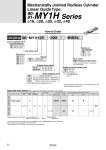
How to Order Linear guide type MY1H Cylinder stroke (mm) Bore size 16 mm 20 mm 25 mm 32 mm 40 mm 16 20 25 32 40 Linear guide type 25 300 M9BWL Stroke adjusting unit Without adjusting unit With low load shock absorber + Adjusting bolt With high load shock absorber + Adjusting bolt With one L unit and one H unit each Nil L H LH Note) MY1H16 is not available with H unit. 90 o16, o20, o25, o32, o40 MY1H Series 90- 91- 90- 91- 16, 20 25, 32, 40 50, 100, 150, 200 250, 300, 350, 400 450, 500, 550, 600 Applicable Auto Switch/Refer to pages 62 to 65 for further information on auto switches. Type Special function Electrical entry Wiring (Output) Load voltage Auto switch model Lead wire length (m) DC AC Perpendicular In-line Applicable load Pre-wired connector Diagnostic indication (2-color indication) Grommet Yes No 2-wire 100 V or less 24 V 12 V Relay, PLC IC circuit 3(L) SDPC M9BWV M9BW A90 Indicator light Mechanically Jointed Rodless Cylinder Linear Guide Type Piping Standard type Centralized piping type Nil G Both ends One end Suffix for stroke adjusting unit Nil S Note) “S” is applicable for stroke adjusting units L and H. Auto switch Nil Without auto switch (Built-in magnet) *Refer to the table below for the applicable auto switch model. 2 pcs. 1 pc. “n” pcs. Number of auto switches Nil S n Reed switch Solid state switch . . . . . *Additional symbols for auto switch: Lead wire length 3 m・・・・・・・・・・・・・・・・・L Example: M9BWL With pre-wired connector・・・・・・・・・・SDPC M9BWSDPC *Order part numbers for auto switches alone are D-M9BW(V)L-900, D-M9BW(V)SDPC-900 and D-A90L-900. *The auto switch is shipped together but not assembled. *Refer to pages 66 to 68 for details on the auto switch mounting brackets. *Specifications and dimensions for the 90-series are the same as standard products. Series compatible with secondary batteries 90 91 Material restriction With lub-retainer 22