【DO!BOOK・ページリンク】
p-e13-12-arc   93 / 143

BOOKをみる

10秒後にBOOKのページに移動します


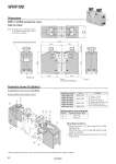
w t r e q y A protective cover can be retrofitted. Dimensions WRF100-T200C WRF- C/With protective cover TS ュ Protective Cover Kit (Option) WRF100-S130 WRF100-T200 WRF100-S200 WRF100-T240 WRF100-S240 WRF100-T270 WRF-C130 WRF-C200 WRF-C240 WRF-C270 r y 3.0 to 4.0 5.0 to 7.0 Tightening torque for cover mounting bolts Applicable product Kit no. Contents q Cover L (1 pc.) w Cover R (1 pc.) e Top covers (2 pcs.) r Hexagon head bolts (4 pcs.) t Flat washers (4 pcs.) y Cover mounting bolts (8 pcs.) Location Tightening torque (N.m) 1. 2. Mount the cover L (q) and cover R (w) on the cylinder body. Mount the cover L (q) on the side where a limit switch is mounted. Mount the top covers (e) to the cover L (q) and cover R (w). . When mounting the protective cover, confirm that all air has been exhausted from inside the cylinder. Fixing method for protective covers Note) Protective cover dimensions shown in the figures are the same even if arm types are different. Limit switch mounting side LED inspection window for limit switch Piping entry 268.6 195.6 153.6 249.6 207.6 459.2 (270) Cover L 6.6 (Max.) Cover R 144.2 148.8 WRF100 85