es70-51a-vxz 44 / 46
10秒後にBOOKのページに移動します
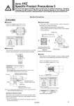
View A-A (Internal connection diagram) . Mark + Mark Round head combination screw M3 Tightening torque 0.5 to 0.6 N・m 2- 1 + Round head combination screw M3 Tightening torque 0.5 to 0.6 N・m Terminal cover A Conduit terminal G1/2 Tightening torque 0.5 to 0.6 N・m A Conduit terminal In the case of the conduit terminal, make connections according to the marks shown below. ・ Use the tightening torques below for each section. ・ Properly seal the terminal connection (G1/2) with the special wiring conduit etc. Class B coil: AWG20 Insulator O.D. 2.5 mm Class H coil: AWG18 Insulator O.D. 2.1 mm Lead wire q Wiring conduit Seal (Bore size G1/2 Tightening torque 0.5 to 0.6 N・m) w Conduit When used as an IP65 equivalent, use seal to install the wiring conduit. Also, use the tightening torque below for the conduit. . There is no polarity. (For the power saving type, there is polarity.) Note) Please order separately. Rated voltage DC 100 VAC 200 VAC Other AC q Black Blue Red Gray w Red Blue Red Gray Lead wire color Description Seal VCW20-15-6 Part no. q w Rubber seal Washer Connector Binding head screw with flange Tightening torque 0.5 to 0.6 N・m Gasket Binding head screw Tightening torque 0.5 to 0.6 N・m Compatible cable Note) (Cable O.D. o6 to o12 mm) 2 3 + . 1 2: . (+) 1: + (.) DIN terminal Since internal connections are as shown below for the DIN terminal, make connections to the power supply accordingly. Caution Grommet Class B coil: AWG20 Insulator O.D. 2.5 mm Class H coil: AWG18 Insulator O.D. 2.1 mm . There is no polarity. ・ Use compatible heavy duty cords with cable O.D. of o6 to 12 mm. ・ Use the tightening torques below for each section. Rated voltage DC 100 VAC 200 VAC Other AC q Black Blue Red Gray w Red Blue Red Gray Lead wire color Terminal no. DIN terminal 1 + (.) 2 . (+) Note) For an outside cable diameter of o9 to 12 mm, remove the internal parts of the rubber seal before using. . There is no polarity. Electrical Connections [Change of electrical entry] Wire entry can be changed by mounting the housing in either direction (four directions at every 90° ) after dividing the terminal block and the housing. . For the indicator lighted style, be careful not to damage the light with the lead wire of the cable. Series VXZ Specific Product Precautions 5 Be sure to read before handling. Refer to back cover for Safety Instructions, “Handling Precautions for SMC Products” (M-E03-3) and the Operation Manual for 2 Port Solenoid Valves for Fluid Control Precautions. Please download it via our website, http://www.smcworld.com 41