es70-44c-vx2 12 / 55
10秒後にBOOKのページに移動します
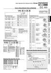
VX2 A 0 A A Common Specifications NBR Class B Seal material Coil insulation type Coil size/Valve type Body material/Orifice diameter Voltage/Electrical entry Size Symbol Size 1 Valve type Symbol ABC AB AB AD N.C. N.O. Body material Orifice diameter 2 3 5 4 7 5 7 Symbol A B C D E F G H J K L M N P Q R S T U V W Y Z Electrical entry Other voltages Voltage 24 VDC 100 VAC 110 VAC 200 VAC 230 VAC 24 VDC 24 VDC 100 VAC 110 VAC 200 VAC 230 VAC 24 VDC 100 VAC 110 VAC 200 VAC 230 VAC 24 VDC 100 VAC 110 VAC 200 VAC 230 VAC 24 VDC Faston terminal Grommet Grommet DIN terminal Conduit terminal Conduit With surge voltage suppressor With surge voltage suppressor With surge voltage suppressor With surge voltage suppressor Size 2 BE N.C. N.O. Size 3 CF N.C. N.O. Resin Resin Resin Dimensions → Page 33 VVX2 1 0 A 02 Coil size Base material/Port size/Base type Size Symbol Size 1 Size 2 Size 3 Symbol AB 1/8 1/4 123 Base material Base type Individual port size Aluminum Common SUP Symbol Nil ABDEZ Rc G NPT G NPT Rc . . . Oil-free Special thread Stations Symbol 02 03 04 05 06 07 08 09 10 Stations 2 stations 3 stations 4 stations 5 stations 6 stations 7 stations 8 stations 9 stations 10 stations Manifold Base/How to Order Blanking Plate Assembly Part No. How to Order Manifold Assembly (Example) NF NBR FKM Seal material For size 1 VVX021S 4A For size 2 VVX022S 4A For size 3 VVX023S 4A When mounting a blanking plate assembly, if the solenoid valve for the manifold is ozone resistant, (Seal material: FKM), please select FKM. For special options, refer to pages 21 to 23. 24 VAC 48 VAC 220 VAC 240 VAC 12 VDC Special voltage DIN terminal with light Conduit terminal with light Without DIN connector Seal material: EPDM Low concentration ozone resistant (Seal material: FKM) Oil-free Special electrical entry direction Common port size: 3/8 (IN port) NNN Fluid 0 Air Fluid 0 Air How to Order (Solenoid Valve for Manifold) Mounting orientation exists when mounting valves onto manifold base. Refer to page 46 for details. Caution D side Stations 5 x Rc1/4 (Individual port)