es40-57-hrsh 4 / 37
10秒後にBOOKのページに移動します
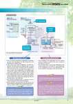
Circuit diagram Refrigeration circuit Circulating fluid circuit Facility water circuit ! The DC inverter compressor compresses the refrigerant gas, and discharges the high temperature and high pressure refrigerant gas. ! In the case of air-cooled refrigeration, the high temperature and high pressure refrigerant gas is cooled down by an air-cooled condenser with the ventilation of the DC inverter fan, and becomes a liquid. In the case of water-cooled refrigeration, the refrigerant gas is cooled by a water-cooled condenser with the facility water in the facility water circuit, and becomes a liquid. ! The liquefied high pressure refrigerant gas expands and its temperature lowers when it passes through expansion valve A and vaporizes by taking heat from the circulating fluid in the evaporator. ! The vaporized refrigerant gas is sucked into the DC inverter compressor and compressed again. ! When heating the circulating fluid, the high pressure and high temperature refrigerant gas is bypassed into the evaporator by expansion valve B, to heat the circulating fluid. ! The circulating fluid discharged from the inverter pump, is heated or cooled by the user’s equipment and returns to the tank. ! The circulating fluid is sent to the evaporator by the inverter pump, and is controlled to a set temperature by the refrigeration circuit, to be discharged to the user’s equipment side again by the thermo-chiller. Adjusting the discharge pressure by pump inverter control eliminates wasteful discharge of the circulating fluid and realizes energy saving operation. Since the refrigeration circuit is controlled by the signal from 2 temperature sensors (for return and discharge), precise temperature control of the circulating fluid can be performed. Therefore, there is no necessity of absorbing the temperature difference in the circulating fluid with a large tank capacity, and realizes high temperature stability even with a small-size tank. Also, contributes to space-saving. POINT POINT The combination of inverter control of the compressor and fan (facility water flow control by a water regulating valve is used in water-cooled refrigeration), and the precise control of expansion valves A and B realizes energy saving operation without waste and high temperature stability. POINT Refrigeration circuit Circulating fluid circuit 2 Thermo-chiller Inverter Type Series HRSH Circulating Fluid Temperature Controller WPR Expansion valve A Pressure sensor (For high-pressure refrigerant gas) Pressure sensor (For low-pressure refrigerant gas) Level switch Ball tap Overflow port Automatic fluid fill port Circulating fluid return port Temperature sensor (For discharge) Temperature sensor (For compressor intake) Pressure sensor (For discharge) Temperature sensor (For return) Drain port Circulating fluid outlet Ventilation Dryer Temperature sensor (For compressor discharge) Evaporator Fluid level indicator User’s equipment (Heat source) Expansion valve B E TS PS TS TS E PS PS TS DC inverter compressor DC inverter fan Inverter pump Ventilation Air-cooled condenser HRSHl-W-l (Water-cooled refrigeration) HRSHl-A-l (Air-cooled refrigeration) D * This circuit construction of the position of the parts may be different from actual product. Water regulating valve Facility water outlet Facility water inlet Water-cooled condenser Air release valve for facility water discharge