es40-57-hrsh@@@3 / 37
10bãÉBOOKÌy[WÉÚ®µÜ·
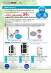
Triple inverter compressor fan pump DC inverter DC inverter Inverter pump Inverter !With caster adjuster-foot ! With earth leakage breaker (400 V type is equipped as standard.) ! With earth leakage breaker with handle (400 V type is equipped as standard.) !With fluid fill port !Piping conversion fitting !Caster adjuster-foot kit !Electric conductivity control set !Bypass piping set ! Snow protection hood (Air-cooled only) Options sPage 22 Optional accessories sPage 25 Air-cooled refrigeration Water-cooled refrigeration Variations The inverter respectively controls the number of motor rotations of the compressor, fan and pump depending on the load from the userfs equipment. With the inverter, it is possible to operate with the same performance even with the power supply of 50 Hz. (The water-cooled type is not equipped with a fan.) * For HRSH250-A-20 Model HRSH100-A HRSH150-A HRSH200-A Cooling capacity 10.5 kW 15.7 kW 20.5 kW Power supply -20 3-phase 200 VAC (50 Hz), 3-phase 200 to 230 VAC (60 Hz) -40 3-phase 380 to 415 VAC (50/60 Hz) Set temp. range 5 to 35C Temp. stability }0.1C Model HRSH100-W HRSH150-W HRSH200-W HRSH250-W Cooling capacity 11.5 kW 15.7 kW 20.6 kW 24 kW Power supply -20 3-phase 200 VAC (50 Hz), 3-phase 200 to 230 VAC (60 Hz) -40 3-phase 380 to 415 VAC (50/60 Hz) Set temp. range 5 to 35C Temp. stability }0.1C Model HRSH250-A HRSH300-A Cooling capacity 25 kW 28 kW Power supply -20 3-phase 200 VAC (50 Hz), 3-phase 200 to 230 VAC (60 Hz) -40 3-phase 380 to 415 VAC (50/60 Hz) Set temp. range 5 to 35C Temp. stability }0.1C Power consumption reduced by 34% compared with a thermo-chiller without the inverter Conditions !Outdoor air temperature: 32C !Circulating fluid temperature setting: 20C !Heat load in the userfs equipment: 25 kW !Power supply: 200 V 60 Hz !Circulating fluid flow rate: 60 L/min@0.5 MPa to the userfs equipment !External piping: The shortest distance assumed to the userfs equipment ! Values shown in the graph for a thermo-chiller without inverter are found by calculation based on an assumption that a thermo-chiller is operated with a general refrigerant circuit that controls the compressor by turning the power ON/OFF, and with a bypass to the circulating fluid circuit. * Cooling capacities ranging from 10 kW to 25 kW 1 Thermo-chiller Inverter Type Series HRSH Circulating Fluid Temperature Controller Low High Low High Low High Load Low High Load Motor rotation rate Without inverter Motor rotation rate Keeps high frequency rotation all the time, and wastes power. The number of motor rotations is controlled depending on the load. Built-in triple inverter A