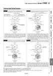
Example 1 The stopper ring is mounted on the standard position. (Rotary actuator with a rotating angle of 270° is used.) Example 2 The stopper ring is mounted on 120° counterclockwise from the standard position shown in Fig. 1-2 of Example 1. (195°) End w End q Counterclockwise Clockwise Set range of Block C = 135° Set range of Block D = 90° A port B port A port B port Stopper ring Block C Single flat Block D End r End e (45°) Set range of Block C Max. 115° (Size: 10, 40) Max. 120° (Size: 15, 20, 30) Set range of Block D Max. 115° (Size: 10, 40) Max. 120° (Size: 15, 20, 30) Point zero Counterclockwise Clockwise End q End w Single flat A port B port A port B port Block C Hatched area represents a stopper lever. Block D Stopper ring Lock Block D in Fig. 1-2, and move Block C clockwise to allow the rotation of the shaft with single flat in Fig. 1-1 from point zero to End q. When Block C is locked and Block D is moved counterclockwise, the shaft with single flat in Fig. 1-1 rotates from point zero to End w. The maximum rotation range of the shaft with single flat is as follows: Sizes 10, 40: up to 230°; Sizes 15, 20, 30: up to 240° (Fig. 1-2 shows when the rotating angle is 0°.) The maximum rotation range of the shaft with single flat in Fig. 2-2 is 195°, from End q to End w. The rotation range of the shaft with single flat in Fig. 2-1 decreases to the range between End w and e when moving Block C in Fig. 2-2 clockwise, and similarly when moving Block D counterclockwise, the rotation range decreases to the range between End q and r. However, since the internal stopper will come into contact with the vane at End q position of the shaft with single flat in Fig. 2-1, make sure that the stopper lever stops at Block D when adjusting. Example 3 The stopper ring is mounted on 120° clockwise from the standard position shown in Fig. 1-2 of Example 1 as in Fig. 4-2 of Example 4. Example 4 The stopper ring is mounted on 120° clockwise from the standard position shown in Fig. 1-2 of Example 1 as in Fig. 3-2 of Example 3. (135°) End w End q Counterclockwise Clockwise Stopper ring Block C Block D A port B port A port B port Single flat Set range of Block C = 30° (45°) (270°) End q End w Counterclockwise Clockwise Single flat A port A port B port Set range of Block C = 90° B port Stopper ring Block C (45°) Lock Block C in Fig. 3-2 and move Block D counterclockwise to allow the rotation of the shaft with single flat in Fig. 3-1 from End q to End w. However, since the internal stopper will come into contact with the vane at End q position of the shaft with single flat make sure that the stopper lever stops at Block C when adjusting. End q side can be adjusted within 30° by moving Block C counterclockwise. The maximum rotation range of the shaft with single flat is 270°, from End q to End w, when using the actuator for 270° and End q side in Fig. 4-1 is stopped using the internal stopper and End w side is adjusted using Block C.�The rotation range can be adjusted within 90° in End w side. Note that Block C cannot be moved and set 90° or more counterclockwise from its position in Fig. 4-2 since the internal stopper will come into contact with the vane. Note 1) Mounting of the stopper ring shown in Examples 2, 3, 4 are not applicable for size 10. Note 2) marks in the illustrations above indicate the mounting position of the stopper ring. Note 3) Select the appropriate rotation of the rotary actuator after careful consideration of the content of “Angle Adjustment Setting”. Note 4) For size 40, each block comes with 2 holding screws. Note 5) These figures show the CRB2 series. Rotating Angle Setting Examples 51 Angle Adjustment Setting Series CRB2 Angle Adjustment CRBU2WU CRBU2 CRB2WU CRB2 With Auto Switch Setting Component Unit Made to Order Simple Specials