es20-230b-crb2 44 / 60
10秒後にBOOKのページに移動します
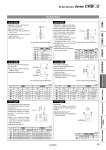
The above figure shows the CRB2 series. d1 = o The above figure shows the CRB2 series. Short shaft side Long shaft side Body (B) Body (A) Y = X= E1 = E3 = L1 = L3 = X = The above figure shows the CRB2 series. Q1 = M Q1 L1 = L1 The above figure shows the CRB2 series. Body (A) Body (B) Y = X = LL Key dimensions LL Double Shaft Symbol: A13 Applicable to single vane type only. Shaft with through-hole 傱 Not available for size 10 傱 Minimum machining diameter for d1 is 0.1 mm. 傱 A parallel key is used on the long shaft for size 40. 傱 Applicable shaft type: W (mm) Size CRB2, CRBU2 d1 15 o2.5 20 o2.5 to o3.5 30 o2.5 to o4 40 o2.5 to o3 Symbol: A19 Both the long shaft and short shaft are shortened. 傱 A parallel key is used on the long shaft for size 40. 傱 Applicable shaft type: W (mm) Size CRB2 CRBU2 X Y X Y 10 3 to 14 1 to 8 1 to 14 1 to 8 15 4 to 18 1.5 to 9 1.5 to 18 1.5 to 9 20 4.5 to 20 1.5 to 10 1.5 to 20 1.5 to 10 30 5 to 22 2 to 13 2 to 22 2 to 13 40 18 to 30 4.5 to 15 18 to 30 4.5 to 15 Symbol: A23 The long shaft can be further shortened by machining right-angle double-sided chamfer onto it. (If altering the standard chamfer and shortening the shaft are not required, indicate “*” for both the L1 and X dimensions.) 傱 Since L1 is a standard chamfer, dimension E1 is 0.5 mm or more, and 1 mm or more with a shaft bore size of o30 and o40. 傱 Applicable shaft type: W (mm) Size CRB2 CRBU2 X L1 L3 max X L1 L3 max 10 5 to 14 9-(14-X) to (X-3) X-3 3 to 14 9-(14-X) to (X-1) X-1 15 8 to 18 10-(18-X) to (X-4) X-4 3 to 18 10-(18-X) to (X-1.5) X-1.5 20 10 to 20 10-(20-X) to (X-4.5) X-4.5 3 to 20 10-(20-X) to (X-1.5) X-1.5 30 10 to 22 12-(22-X) to (X-5) X-5 5 to 22 12-(22-X) to (X-2) X-2 Symbol: A16 (mm) Size Thread CRB2, CRBU2 15 20 30 40 M3 x 0.5 o2.5 o2.5 o2.5 o2.5 M4 x 0.7 . o3.3 o3.3 . M5 x 0.8 . . o4.2 . Symbol: A20 The shafts are reversed. (Both the long shaft and the short shaft are shortened.) 傱 A parallel key is used on the long shaft for size 40. 傱 Applicable shaft type: W 傱 Dimensions inside ( ) are for double vane type of size 10. (mm) Size CRB2 CRBU2 X Y X Y 10 3 to 10 (19) 1 to 12 (3) 1 to 3 (12) 1 to 19 (10) 15 4 to 11.5 1.5 to 15.5 1.5 to 6.5 1.5 to 20.5 20 4.5 to 13 1.5 to 17 1.5 to 7.5 1.5 to 22.5 30 5 to 16 2 to 19 2 to 8.5 2 to 26.5 40 6.5 to 17 16 to 28 3 to 9 24 to 36 Symbol: A24 Double key Keys and keyways are machined additionally at 180° from the standard position. 傱 Applicable shaft type: W 傱 Equal dimensions are indicated by the same marker. (mm) Size CRB2, CRBU2 Key dimensions LL 40 4 x 4 x 20 2 Applicable to single vane type only. A special end is machined onto both the long and short shafts, and a through-hole is drilled into both shafts. Female threads are machined into the through-holes, whose diameter is equivalent to the diameter of the pilot holes. 傱 Not available for size 10 傱 The maximum dimension L1 is, as a rule, twice the thread size. (Example) For M5: L1 max. = 10 mm 傱 A parallel key is used on the long shaft for size 40. 傱 Applicable shaft type: W 傱 Equal dimensions are indicated by the same marker. 39 Simple Specials Series CRB𡱖2 Angle Adjustment CRBU2WU CRBU2 CRB2尰WU CRB2 With Auto Switch Setting Component Unit Made to Order Simple Specials A