es20-230b-crb2 43 / 60
10秒後にBOOKのページに移動します
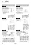
Q1 = M L1 = The above figure shows the CRB2 series. The above figure shows the CRB2 series. Body (A) Body (B) Long shaft side Short shaft side X = D1 = o The standard chamfer may not be altered depending on the type of machining required. E1 = E3 = L1 = C1 = L3 = X = C1 Q2 = M L2 = The above figure shows the CRB2 series. The above figure shows the CRB2 series. Body (A) Body (B) Long shaft side Short shaft side Y = The standard chamfer may not be altered depending on the type of machining required. D2 = o E2 = E4 = L4 = C2 C2 = L2 = Y2 = Axial: Top (Long shaft side) Axial: Bottom (Short shaft side) Symbol: A14 Applicable to single vane type only. A special end is machined onto the long shaft, and a through-hole is drilled into it. Female threads are machined into the through-hole, whose diameter is equivalent to the pilot hole diameter. 傱 Not available for size 10 傱 The maximum dimension L1 is, as a rule, twice the thread size. (Example) For M3: L1 max. = 6 mm 傱 A parallel key is used on the long shaft for size 40. 傱 Applicable shaft type: W (mm) Size Thread CRB2, CRBU2 15 20 30 40 M3 x 0.5 o2.5 o2.5 o2.5 o2.5 M4 x 0.7 . o3.3 o3.3 . M5 x 0.8 . . o4.2 . Symbol: A17 The long shaft is shortened. 傱 Applicable shaft type: W (mm) Size CRB2 CRBU2 X X 10 3 to 14 1 to 14 15 4 to 18 1.5 to 18 20 4.5 to 20 1.5 to 20 30 5 to 22 2 to 22 40 18 to 30 18 to 30 Symbol: A21 The long shaft can be further shortened by machining it into a stepped round shaft with a double-sided chamfer. (If shortening the shaft is not required, indicate “*” for dimension X.) 傱 Applicable shaft type: W 傱 Equal dimensions are indicated by the same marker. (If not specifying dimension C1, indicate “*” instead.) mm Size CRB2 CRBU2 X L1 max L3 D1 X L1 max L3 D1 10 6 to 14 X-4.5 L1+1.5 o3 4 to 14 X-2.5 L1 + 1.5 o3 15 7 to 18 X-5.5 L1+1.5 o3 to o4 4.5 to 18 X-3 L1 + 1.5 o3 to o4 20 8 to 20 X-6.5 L1+2 o3 to o5 5 to 20 X-3.5 L1 + 2 o3 to o5 30 10 to 22 X-8 L1+3 o3 to o6 7 to 22 X-5 L1 + 3 o3 to o6 Symbol: A15 Applicable to single vane type only. A special end is machined onto the short shaft, and a through-hole is drilled into it. Female threads are machined into the through-hole, whose diameter is equivalent to the pilot hole diameter. 傱 A parallel key is used on the long shaft for size 40. 傱 Not available for size 10 傱 The maximum dimension L2 is, as a rule, twice the thread size. (Example) For M4: L2 max. = 8 mm 傱 Applicable shaft type: W (mm) Size Thread CRB2, CRBU2 15 20 30 40 M3 x 0.5 o2.5 o2.5 o2.5 o2.5 M4 x 0.7 . o3.3 o3.3 . M5 x 0.8 . . o4.2 . Symbol: A18 The short shaft is shortened. 傱 A parallel key is used on the long shaft for size 40. 傱 Applicable shaft type: W (mm) Size CRB2, CRBU2 Y 10 1 to 8 15 1.5 to 9 20 1.5 to 10 30 2 to 13 40 4.5 to 15 Symbol: A22 The short shaft can be further shortened by machining it into a stepped round shaft with a double-sided chamfer. (If shortening the shaft is not required, indicate “*” for dimension Y.) 傱 Applicable shaft type: W 傱 Equal dimensions are indicated by the same marker. (If not specifying dimension C2, indicate “*” instead.) (mm) Size CRB2, CRBU2 Y L1 max L4 D2 10 4 to 8 Y-2.5 L2 + 1.5 o3 15 4.5 to 9 Y-3 L2 + 1.5 o3 to o4 20 5 to 10 Y-3.5 L2 + 2 o3 to o5 30 7 to 13 Y-5 L2 + 3 o3 to o6 40 8 to 15 Y-5.5 L2 + 5 [L2 + 3] Note) o3 to o6 Note) Values inside [ ] are for the CRBU2. 38 Series CRB𡱖2