es20-230b-crb2 42 / 60
10秒後にBOOKのページに移動します
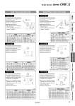
Q1 = M C1 = C L1-(3 x P) X = L1 = X = L1 = E1 = E3 = L1 = L3 = X = Q2 = M L2 = C2 = C L2-(3 x P) Y = L2 = Y = L4 = L2 = E2 = E4 = Y= Axial: Top (Long shaft side) Axial: Bottom (Short shaft side) Symbol: A7 The long shaft can be further shortened by machining it into a stepped round shaft with male threads. (If shortening the shaft is not required, indicate “*” for dimension X.) 傱 Applicable shaft type: W 傱 Equal dimensions are indicated by the same marker. (If not specifying dimension C1, indicate “*” instead.) (mm) Size CRB2 CRBU2 X L1 max Q1 X L1 max Q1 10 7.5 to 14 X-3 3 5.5 to 14 X-1 3 15 10 to 18 X-4 3, 4 7.5 to 18 X-1.5 3 20 12 to 20 X-4.5 3, 4, 5 9 to 20 X-1.5 3, 4 30 14 to 22 X-5 3, 4, 5, 6 11 to 22 X-2 3, 4, 5, 6 Symbol: A9 The long shaft can be further shortened by changing the length of the standard chamfer on the long shaft side. (If shortening the shaft is not required, indicate “*” for dimension X.) 傱 Applicable shaft type: W (mm) Size CRB2 CRBU2 X L1 X L1 10 5 to 14 9-(14-X) to (X-3) 3 to 14 9-(14-X) to (X-1) 15 8 to 18 10-(18-X) to (X-4) 5.5 to 18 10-(18-X) to (X-1.5) 20 10 to 20 10-(20-X) to (X-4.5) 7 to 20 10-(20-X) to (X-1.5) 30 10 to 22 12-(22-X) to (X-5) 7 to 22 10-(22-X) to (X-2) Symbol: A11 The long shaft can be further shortened by machining a double-sided chamfer onto it. (If altering the standard chamfer and shortening the shaft are not required, indicate “*” for both the L1 and X dimensions.) 傱 Since L1 is a standard chamfer, dimension E1 is 0.5 mm or more, and 1 mm or more with a shaft bore size of o30. 傱 Applicable shaft type: W (mm) Size CRB2 CRBU2 X L1 L3 max X L1 L3 max 10 5 to 14 9-(14-X) to (X-3) X-3 3 to 14 9-(14-X) to (X-1) X-1 15 8 to 18 10-(18-X) to (X-4) X-4 3 to 18 10-(18-X) to (X-1.5) X-1.5 20 10 to 20 10-(20-X) to (X-4.5) X-4.5 3 to 20 10-(20-X) to (X-1.5) X-1.5 30 10 to 22 12-(22-X) to (X-5) X-5 5 to 22 12-(22-X) to (X-2) X-2 Symbol: A8 The short shaft can be further shortened by machining it into a stepped round shaft with male threads. (If shortening the shaft is not required, indicate “*” for dimension Y.) 傱 Applicable shaft type: W 傱 Equal dimensions are indicated by the same marker. (If not specifying dimension C2, indicate “*” instead.) (mm) Size CRB2, CRBU2 Y L2 max Q2 10 5.5 to 8 Y-1 3 15 7.5 to 9 Y-1.5 3, 4 20 9 to 10 Y-1.5 3, 4, 5 30 11 to 13 Y-2 3, 4, 5, 6 40 14 to 15 Y-4.5 3, 4, 5, 6, 8 Symbol: A10 The short shaft can be further shortened by changing the length of the standard chamfer on the short shaft side. (If shortening the shaft is not required, indicate “*” for dimension Y.) 傱 Applicable shaft type: W (mm) Size CRB2, CRBU2 Y L2 10 3 to 8 5-(8-Y) to (Y-1) 15 3 to 9 6-(9-Y) to (Y-1.5) 20 3 to 10 7-(10-Y) to (Y-1.5) 30 5 to 13 8-(13-Y) to (Y-2) 40 7 to 15 9-(15-Y) to (Y-2) [9-(15-Y) to (Y-4.5)] Note) Note) Values inside [ ] are for the CRBU2. Symbol: A12 The short shaft can be further shortened by machining a double-sided chamfer onto it. (If altering the standard chamfer and shortening the shaft are not required, indicate “*” for both the L2 and Y dimensions.) 傱 Since L2 is a standard chamfer, dimension E2 is 0.5 mm or more, and 1 mm or more with shaft bore size of o30 and o40. 傱 Applicable shaft type: W (mm) Size CRB2, CRBU2 Y L2 L4 max 10 3 to 8 5-(8-Y) to (Y-1) Y-1 15 3 to 9 6-(2-Y) to (Y-1.5) Y-1.5 20 3 to 10 7-(10-Y) to (Y-1.5) Y-1.5 30 5 to 13 8-(13-Y) to (Y-2) Y-2 40 7 to 15 9-(15-Y) to (Y-4.5) Y-4.5 37 Simple Specials Series CRB𡱖2 Angle Adjustment CRBU2WU CRBU2 CRB2尰WU CRB2 With Auto Switch Setting Component Unit Made to Order Simple Specials