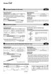
ZZ + 2 x Stroke S + Stroke HA + Stroke 20 Even if driving at lower speeds 5 to 50 mm/s, there would be no stick-slip phenomenon and it can run smoothly. 4 Low Speed Cylinder (5 to 50 mm/s) -XB13 Symbol Description Model Action Note Standard type CJ2 Double acting, Single rod o6 only Piston speed 5 to 50 mm/s Dimensions Same as standard type Additional specifications Same as standard type Applicable Series Specifications Note 1) Operate without lubrication from a pneumatic system lubricator. Note 2) For the speed adjustment, use speed controllers for controlling at lower speeds. (Series AS-FM/AS-M) Be aware that smoking cigarettes etc. after your hands have come into contact with the grease used in this cylinder can create a gas that is hazardous to humans. Precautions Warning Standard model no. XB13 How to Order Low speed cylinder Compared with the standard type, a cylinder which changes the connection port location of rod/head cover. 5 Special Port Location -XC3 Symbol Special port location Rod port location viewed from the rod side Head port location viewed from the rod side * For port location, refer to the diagrams on the right and show the symbols of A, B, C and D. How to Order Standard model no. XC3 A B Corresponding symbol of mounting bracket (Positional relationships) B C D A Port D C B A Port Applicable Series Description Model Action Note Standard type CJ2 Double acting, Single rod Except with rail mounting type auto switches, with air cushion Non-rotating rod type CJ2K Double acting, Single rod Except with rail mounting type auto switches Specifications: Same as standard type * Viewed from the rod side, the ports are rendered A, B, C, and D, in the clockwise direction. * Viewed from the rod side, with the clevis positioned as shown in the diagram, the ports are rendered A, B, C, and D, in the clockwise direction. Port Location Dimensions (Dimensions other than below are the same as standard type.) * Dimensions except mentioned above are the same as standard type. (mm) Bore size Applicable stroke HA S ZZ 10 15 to 150 37 49 114 16 15 to 200 37 50 115 It adjusts the extending stroke by the stroke adjustable mechanism equipped in the head side. (After the stroke is adjusted, with cushion on both sides is altered to single-sided, with cushion.) 6 Adjustable Stroke Cylinder/Adjustable Extension Type -XC8 Symbol Applicable Series Description Model Action Note Standard type CJ2 Double acting, Single rod Except with air cushion, double-side bossed, double clevis, double foot, head flange. Specifications Stroke adjustment symbol . Stroke adjustment range (mm) 0 to 15 Additional specifications Same as standard type Stroke adjustable mechanism Standard model no. Adjustable stroke cylinder/ Adjustable extension type How to Order XC8 1. When the cylinder is operating, if something gets caught between the stopper bracket for adjusting the stroke and the cylinder body, it could cause bodily injury or damage the peripheral equipment. Therefore, take preventive measures as necessary, such as installing a protective cover. 2. To adjust the stroke, make sure to secure the wrench flats of the stopper bracket by a wrench etc. before loosening the lock nut. If the lock nut is loosened without securing the stopper bracket, be aware that the area that joins the load to the piston rod or the area in which the piston rod is joined with the load side and the stopper bracket side could loosen first. It may cause an accident or malfunction. Precautions Warning 111 Series CJ2