es20-224-cg1 26 / 96
10秒後にBOOKのページに移動します
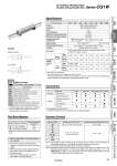
Air cushion Rubber bumper Symbol . R: Rod side, H: Head side .. Rod trunnion type is not available for o80 and o100. Foot and flange types of cylinder sizes from o20 to o63 do not have trunnion mounting female thread. Operate the cylinder within the allowable kinetic energy. Bore size (mm) 20 25 32 40 50 63 80 100 Action Double acting, Double rod Lubricant Not required (Non-lube) Fluid Air Proof pressure 1.5 MPa Maximum operating pressure 1.0 MPa Minimum operating pressure 0.08 MPa Ambient and fluid temperature Without auto switch: .10°C to 70°C (No freezing) With auto switch : .10°C to 60°C Piston speed 50 to 1000 mm/s 50 to 700 mm/s Stroke length tolerance Up to 1000 st +1.4 0 mm, Up to 1500 st +1.8 0 mm Cushion Rubber bumper, Air cushion Mounting.* Basic, Basic (without trunnion mounting female thread), Axial foot, Flange, Trunnion Allowable kinetic energy (J) Rubber bumper Male rod end 0.28 0.41 0.66 1.20 2.00 3.40 5.90 9.90 Female rod end 0.11 0.18 0.29 0.52 0.91 1.54 2.71 4.54 Air cushion Male rod end R: 0.35 H: 0.42 R: 0.56 H: 0.65 0.91 1.80 3.40 4.90 11.80 16.70 Female rod end 0.11 0.18 0.29 0.52 0.91 1.54 2.71 4.54 Specifications .1 Cylinders with rubber bumper have no bumper. .2 Only compatible with cylinders with rubber bumper, but has no bumper. Symbol Specifications -XAl Change of rod end shape -XB6 Heat resistant cylinder (.10 to 150°C).1 -XB7 Cold resistant cylinder (.40 to 70°C).2 -XC6 Made of stainless steel -XC13 Auto switch rail mounting -XC22 Fluororubber seal.1 -XC37 Larger throttle diameter of connection port -XC85 Grease for food processing equipment Made to Order (For details, refer to pages 77 to 93.) . Maximum ambient temperature for the rod boot itself. Symbol Rod boot material Maximum operating temperature J Nylon tarpaulin 70°C K Heat resistant tarpaulin 110°C. Rod Boot Material Refer to pages 68 to 74 for cylinders with auto switches. . Auto switch proper mounting position (detection at stroke end) and its mounting height . Minimum stroke for auto switch mounting . Auto switch mounting brackets/Part no. . Operating range . Cylinder mounting bracket, by stroke/ Auto switch mounting surfaces . Not available for o80 and o100. .. A double knuckle joint pin and retaining rings are shipped together. Mounting Basic Axial foot Rod flange Rod trunnion Standard Rod end nut V V V V Option Single knuckle joint V V V V Double knuckle joint.. (with pin) V V V V Pivot bracket. . . . V. Rod boot V V V V Accessories Note 1) Intermediate strokes not listed above are produced upon receipt of order. Manufacture of intermediate strokes at 1 mm intervals is possible. (Spacers are not used.) Note 2) The maximum manufacturable stroke shows the long stroke. Note 3) Applicable strokes should be confirmed according to the usage. For details, refer to “Air Cylinders Model Selection” on front matter pages of the Best Pneumatics No. 2 or the WEB catalog. In addition, the products that exceed the standard stroke might not be able to fulfill the specifications due to the deflection etc. Bore size (mm) Standard stroke (mm) Note1) Maximum manufacturable stroke (mm) Note 2) 20 25, 50, 75, 100, 125, 150, 200 201 to 1500 25 25, 50, 75, 100, 125, 150, 200, 250, 300 301 to 1500 32 40 50, 63 80 100 Standard Strokes 24 Air Cylinder: Standard Type Double Acting, Double Rod Series CG1W CG1Q CBG1 CG1KR CG1R CG1KW CG1K CG1 CG1W CG1 Low Friction With End Lock Direct Mount, Non-rotating Rod Direct Mount Non-rotating Rod Standard Double Acting, Single Rod Double Acting, Single Rod Double Acting, Double Rod Double Acting, Single Rod Single Acting, Spring Return/Extend Double Acting, Double Rod Double Acting, Single Rod Made to Order Auto Switch