es20-224-cg1ü@ü@ü@14 / 96
10ĽbîŃé╔BOOKé╠âyü[âWé╔ł┌ô«éÁé▄éĚ
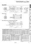
oD oI oI oD C NA C H1 F GA GB TB F TA AL A H K oTD NA TG TE TF GA WA Cushion valve, Width across flats WH GB WB H1 F GA GB H F A AL K 8 x J oE 0 .0.05 ZZ + Stroke S + Stroke 4 x TC 2 x TC R0.4 R0.4 oE 0 .0.05 Width across flats B1 MM Width across flats KA 2 x P (Rc, NPT, G) 10üő WâĂüő 2 x P (Rc, NPT, G) Width across flats B1 oE 0 .0.05 R0.4 2 x P (Rc, NPT, G) R0.4 oE 0 .0.05 S + Stroke ZZ + Stroke MM Width across flats KA Basic: CG1BN With air cushion Basic (Without trunnion mounting female thread): CG1ZN TC thread detail (mm) (mm) Bore size Stroke range Rc, NPT port G port A AL B1 C D E F H H1 I J K KA MM Standard Long stroke GA GB P GA GB P 20 Up to 200 201 to 1500 12 10 (12) 1/8 12 10 (12) M5 x 0.8 18 15.5 13 14 8 12 2 35 5 26 M4 x 0.7 depth 7 5 6 M8 x 1.25 25 Up to 300 301 to 1500 12 10 (12) 1/8 12.5 10 (12.5) M5 x 0.8 22 19.5 17 16.5 10 14 2 40 6 31 M5 x 0.8 depth 7.5 5.5 8 M10 x 1.25 32 Up to 300 301 to 1500 12 10 (12) 1/8 10.5 10 (10.5) 1/8 22 19.5 17 20 12 18 2 40 6 38 M5 x 0.8 depth 8 5.5 10 M10 x 1.25 40 Up to 300 301 to 1500 13 10 (13) 1/8 13 10 (10) 1/8 30 27 19 26 16 25 2 50 8 47 M6 x 1 depth 12 6 14 M14 x 1.5 50 Up to 300 301 to 1500 14 12 (14) 1/4 14 12 (14) 1/4 35 32 27 32 20 30 2 58 11 58 M8 x 1.25 depth 16 7 18 M18 x 1.5 63 Up to 300 301 to 1500 14 12 (14) 1/4 14 12 (14) 1/4 35 32 27 38 20 32 2 58 11 72 M10 x 1.5 depth 16 7 18 M18 x 1.5 80 Up to 300 301 to 1500 20 16 (20) 3/8 17.5 16 (17.5) 3/8 40 37 32 50 25 40 3 71 13 89 M10 x 1.5 depth 22 10 22 M22 x 1.5 100 Up to 300 301 to 1500 20 16 (20) 1/2 17.5 16 (17.5) 1/2 40 37 41 60 30 50 3 71 16 110 M12 x 1.75 depth 22 10 26 M26 x 1.5 Bore size NA S TA TB ZZ 20 24 69 (77) 11 11 106 (114) 25 29 69 (77) 11 11 111 (119) 32 35.5 71 (79) 11 10 (11) 113 (121) 40 44 78 (87) 12 10 (12) 130 (139) 50 55 90 (102) 13 12 (13) 150 (162) 63 69 90 (102) 13 12 (13) 150 (162) 80 86 108 (122) . . 182 (196) 100 106 108 (122) . . 182 (196) Note) ( ): Denotes the dimensions for long stroke. With Air Cushion (mm) Bore size Rc, NPT, G GA GB P WA WB W âĂ WH 20 12 10 (12) M5 x 0.8 16 15 (16) 25üő 1.5 25 12.5 10 (12.5) M5 x 0.8 16 14.5 (16) 25üő 1.5 32 12 10 (12) 1/8 16 14 (16) 25üő 1.5 40 13 10 (13) 1/8 17 15 (17) 20üő 1.5 50 14 12 (14) 1/4 18 16 (18) 20üő 3 63 14 12 (14) 1/4 18 17 (18) 20üő 3 80 20 16 (20) 3/8 24 20 (24) 20üő 4 100 20 16 (20) 1/2 24 20 (24) 20üő 4 * Cylinder sizes o80 and o100 do not have trunnion mounting female thread on the width across flats NA. TC Thread (mm) Bore size TC TD TE TF TG 20 M5 x 0.8 8+0.08 0 4 0.5 5.5 25 M6 x 0.75 10+0.08 0 5 1 6.5 32 M8 x 1.0 12+0.08 0 5.5 1 7.5 40 M10 x 1.25 14+0.08 0 6 1.25 8.5 50 M12 x 1.25 16+0.08 0 7.5 2 10 63 M14 x 1.5 18+0.08 0 11.5 3 14.5 80 . . . . . 100 . . . . . 12 Air Cylinder: Standard Type Double Acting, Single Rod Series CG1 CG1«Q CBG1 CG1KR CG1R CG1KW CG1K CG1 CG1W CG1 Low Friction With End Lock Direct Mount, Non-rotating Rod Direct Mount Non-rotating Rod Standard Double Acting, Single Rod Double Acting, Single Rod Double Acting, Double Rod Double Acting, Single Rod Single Acting, Spring Return/Extend Double Acting, Double Rod Double Acting, Single Rod Made to Order Auto Switch