es100-111-motorless 81 / 90
10秒後にBOOKのページに移動します
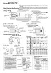
oFD+0.3 +0.1 45° oFC 60 2 x FA thread depth FB FF FE Motor mounting surface [Provided by user] Motor mounting bolt [Provided by user] Motor PP (Mounting distance) [Included parts] Motor pulley [Included parts] Hexagon socket head cap screw/MM1 (Tightening torque: TT1 [N・m]) oPD (I.D.) [Included parts] Hexagon socket head cap screw/2 x MM2 (Tightening torque: TT2 [N・m]) [Included parts] Timing belt (Belt tension/tensile force: BT [N]) [Assembly] Return box [Included parts] Hexagon socket head cap screw/4 x MM3 (Tightening torque: TT3 [N・m]) [Provided by user] Motor [Provided by user] Motor mounting bolt [Included parts] Motor flange oPD (I.D.) [Included parts] Hexagon socket head set screw/MM1 (Tightening torque: TT1[N・m]) . Mount to D-cut surface of the motor shaft. [Included parts] Motor pulley PP (Mounting distance) [Provided by user] Motor [Included parts] Motor flange . Refer to the “Motor flange details.” oPD (I.D.) [Included parts] Hexagon socket head set screw/MM1 (Tightening torque: TT1 [N・m]) . Mount to D-cut surface of the motor shaft. [Provided by user] Motor mounting bolt PP (Mounting distance) [Included parts] Motor flange . Refer to the “Motor flange details.” Motor Mounting: Top Mounting Motor flange details Motor flange Timing belt Return box Motor pulley Body side pulley Return plate Mounting procedure 1) Fix the motor (provided by user) and the “motor pulley” with the “MM1 hexagon socket head cap screw or hexagon socket head set screw.” 2) Fix the motor and the “motor flange” with the motor mounting bolts (provided by user). 3) Put the “timing belt” on the “motor pulley” and “body side pulley”, and then fix it temporarily with the “MM2 hexagon socket head cap screws.” (Refer to the mounting diagram.) 4) Apply the belt tension and tighten the timing belt with the “MM2 hexagon socket head cap screws.” (The reference level is the elimination of the belt deflection.) 5) Fix the “return plate” with the “MM3 hexagon socket head cap screws.” !The motor and motor mounting bolts should be provided by user. !Motor shaft style should be cylindrical for the NZ, NY, NW motor types, and D-cut style for the NM1 motor type. !When mounting a pulley, remove the oil content, dust, or dirt sticking to the shaft and pulley inside diameter. !Take loose prevention measures for the motor mounting bolts and hexagon socket head set screws. M4 x 0.7 M3 x 0.5 o3.4 M5 x 0.8 M4 x 0.7 M4 x 0.7 NZ NY NM1 NZ NY NM1 11 11 8.5 13 13 5 FF 42 42 42 60 60 56.4 FG 3.7 5 3.5 4.6 4.6 . FE 30 30 28 50 50 38.2 FD 46 45 31 70 70 47.1 FC 7.5 5.5 7 8.5 7 (5) Motor type FA FB M2.5 x 10 M3 x 4 M3 x 12 M4 x 12 M3 x 4 1.0 0.63 1.5 2.5 0.63 NZ NY NM1 NZ NY NW NM1 25 32 MM1 TT1 M3 x 8 M4 x 12 MM2 0.63 1.5 Size Motor type TT2 25 32 Size Dimensions [mm] NZ NY NM1 NZ NY NW NM1 25 32 M4 x 10 M6 x 14 MM3 1.5 5.2 TT3 8 5 14 11 9 6.35 PD 7.5 11.8 4.5 7.1 PP 19 30 Size Motor type BT Size: 25, 32 1111 4 2 . 1 1111 4 2 1 . Motor flange Motor pulley Return plate Timing belt Hexagon socket head cap screw (for return plate mounting) Hexagon socket head cap screw (for motor flange mounting) Hexagon socket head cap screw (for pulley fixing) Hexagon socket head set screw (for pulley fixing) NZ, NY, NW NM1 Motor type Quantity Description Included Parts List Motor Mounting Diagram LEY25: NM1 LEY32: NM1 LEY25: NZ, NY LEY32: NZ, NY, NW Motor mounting surface 2 x oFA FB depth, depth of counterbore FE FF oFD FC FC FG FG FC 2 x FA thread depth FB FF oFD FC 2 x (M4 x 0.7) thread depth FB Motor mounting surface LEY , LEYG LEY25, LEYG25: NM1 LEY32, LEYG32: NM1 25 32 25 32 [Included parts] Return plate 77 Series LEY/LEYG