es100-111-motorless 43 / 90
10秒後にBOOKのページに移動します
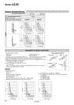
0 200 400 600 800 1000 0 5 10 15 20 0 200 400 600 800 1000 0 5 10 15 20 0 200 400 600 800 1000 0 2 4 6 8 10 0 2 4 6 8 10 0 200 400 600 800 1000 m Me L7 m Me L8 Calculation of Guide Load Factor 1. Decide operating conditions. Model: LEJS Size: 40/63 Mounting orientation: Horizontal/Bottom/Wall/Vertical 2. Select the target graph with reference to the model, size and mounting orientation. 3. Based on the acceleration and work load, obtain the overhang [mm]: Lx/Ly/Lz from the graph. 4. Calculate the load factor for each direction. αx = Xc/Lx, αy = Yc/Ly, αz = Zc/Lz 5. Confirm the total of αx, αy and αz is 1 or less. αx + αy + αz .1 When 1 is exceeded, consider a reduction of acceleration and work load, or a change of the work load center position and series. Y Z Work load [kg] Work load [kg] L8 [mm] L7 [mm] Work load [kg] Work load [kg] L8 [mm] L7 [mm] Load overhanging direction m: Work load [kg] Me: Dynamic allowable moment [N・m] L: Overhang to the work load center of gravity [mm] Model LEJS40 LEJS63 0 200 400 Lx 600 800 1000 0 10 20 30 40 50 L1 [mm] Work load [ kg] 0 200 400 600 800 1000 0 10 20 30 40 50 L2 [mm] Work load [kg] 0 200 400 600 800 1000 0 10 20 30 40 50 L3 [mm] Work load [kg] Ly Lz x y z x z y x z y x y z Dynamic Allowable Moment 1. Operating conditions Model: LEJS Size: 40 Mounting orientation: Horizontal Acceleration [mm/s2]: 5000 Work load [kg]: 20 Work load center position [mm]: Xc = 0, Yc = 50, Zc = 200 2. Select the graph on page 38, top and left side first row. Vertical Orientation Example Acceleration [mm/s2]: a Work load [kg]: m Work load center position [mm]: Xc/Yc/Zc Mounting Orientation 1. Horizontal 3. Wall 2. Bottom 4. Vertical . This graph shows the amount of allowable overhang when the center of gravity of the workpiece overhangs in one direction. When the center of gravity of the workpiece overhangs in two directions, refer to the Electric Actuator Selection Software for confirmation, http://www.smcworld.com Acceleration/Deceleration 5000 mm/s2 15000 mm/s2 10000 mm/s2 20000 mm/s2 3. Lx = 180 mm, Ly = 170 mm, Lz = 360 mm 4. The load factor for each direction can be obtained as follows. αx = 0/180 = 0 αy = 50/170 = 0.29 αz = 200/360 = 0.56 5. αx + αy + αz = 0.85 .1 Series LEJS 39