es100-111-motorless 33 / 90
10秒後にBOOKのページに移動します
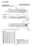
LEFB40U/Motor bottom mounting type Dimensions: Belt Drive Dimensions L A B n D E [mm] 400 400 600 600 800 800 1000 1000 1200 1200 1400 1400 1600 1600 1800 1800 2000 2000 2600 3000 2 2 3 3 4 4 5 5 6 6 7 7 8 8 9 9 10 10 13 15 6 6 8 8 10 10 12 12 14 14 16 16 18 18 20 20 22 22 28 32 478 578 678 778 878 978 1078 1178 1278 1378 1478 1578 1678 1778 1878 1978 2078 2178 2678 3178 306 406 506 606 706 806 906 1006 1106 1206 1306 1406 1506 1606 1706 1806 1906 2006 2506 3006 641.5 741.5 841.5 941.5 1041.5 1141.5 1241.5 1341.5 1441.5 1541.5 1641.5 1741.5 1841.5 1941.5 2041.5 2141.5 2241.5 2341.5 2841.5 3341.5 300 400 500 600 700 800 900 1000 1100 1200 1300 1400 1500 1600 1700 1800 1900 2000 2500 3000 Stroke 33 90 31 61 (68) Belt tension adjustment bolt (M5: Width across flats 8) 76 B D x 200 (= E) 200 60 46 5 6H9 ( ) depth 6 6H9 ( ) depth 7 o6H9 ( ) depth 7 Motor mating part: oFD, depth FE Mounting pitch: oFC 45° 7 n x o6.6 4 x FA thread depth FB Motor Motor flange FF 65.5 60.5 66 (86) A (Table traveling distance) L 6 86 97.5 (12) Body mounting reference plane Note) 60 106 (170) 4 x M8 x 1.25 thread depth 13 7 8 M4 x 0.7 thread depth 8 (F.G. terminal) 7 74 53.8 68 58 Note) When mounting the actuator using the body mounting reference plane, set the height of the opposite surface or pin to be 3 mm or more. (Recommended height 5 mm) Motor Mounting Dimensions [mm] 34 34 37.2 35 21 4 4 4.5. 5 4.5. 50 50 40. 50 38.1. o70 o70 o63 o70 47.14 9 8 9 9 8 M5 x 0.8 M4 x 0.7 M5 x 0.8 M5 x 0.8 M4 x 0.7 NZ NY NX NW NM1 Motor type FA FB FC FD FE FF . Dimensions after mounting a ring spacer (Refer to page 30.) Refer to the “Motor Mounting” on page 30 for details about motor mounting and included parts. +0.030 0 +0.030 0 +0.030 0 29 Series LEFB