es100-111-motorless 23 / 90
10秒後にBOOKのページに移動します
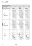
Dynamic Allowable Moment Load overhanging direction m: Work load [kg] Me: Dynamic allowable moment [N・m] L: Overhang to the work load center of gravity [mm] Model LEFB25 LEFB32 LEFB40 L1 L2 Mep m Mey m L3 Mer m 0 500 1000 0 5 10 15 20 0 500 1000 0 5 10 15 20 0 200 400 600 800 0 5 10 15 20 0 500 1000 0 10 20 30 40 0 500 1000 0 10 20 30 40 0 200 400 600 800 0 10 20 30 40 0 500 1000 0 10 20 30 40 50 60 Work load [kg] Work load [kg] Work load [kg] Work load [kg] Work load [kg] Work load [kg] Work load [kg] Work load [kg] Work load [kg] L1 [mm] 0 500 1000 0 10 20 30 40 50 60 L2 [mm] 0 200 400 600 800 0 10 20 30 40 50 60 L3 [mm] L3 [mm] L2 [mm] L1 [mm] L3 [mm] L2 [mm] L1 [mm] Acceleration/Deceleration 1000 mm/s2 3000 mm/s2 5000 mm/s2 10000 mm/s2 20000 mm/s2 Horizontal Orientation Rolling Yawing Pitching Series LEFB . This graph shows the amount of allowable overhang when the center of gravity of the workpiece overhangs in one direction. When the center of gravity of the workpiece overhangs in two directions, refer to the Electric Actuator Selection Software for confirmation, http://www.smcworld.com 19