13-e616-asuni 8 / 9
10秒後にBOOKのページに移動します
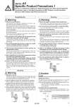
6 Locked Unlocked Body A Elbow body Body B Design/Selection Warning 1. Check the specifications. The products in this catalog are designed to be used in compressed air systems (including vacuum) only. If the products are used in an environment where pressure or temperature is out of the specified range, damage and/or malfunction may result. Do not use under such conditions. (Refer to the specifications.) Please contact SMC when using a fluid other than compressed air (including vacuum). We do not guarantee against any damage if the product is used outside of the specification range. 2. The products in this catalog are not designed for the use as stop valve with zero air leakage. A certain amount of leakage is allowed in the product’s specifications. Tightening the needle to reduce leakage to zero may result in equipment damage. 3. Do not disassemble the product or make any modifications, including additional machining. It may cause human injury and/or an accident. 4. The flow-rate characteristics for each product are representative values. The flow-rate characteristics are characteristics of each individual product. Actual values may differ depending on the piping, circuitry, pressure conditions, etc. 5. Sonic conductance (C) and critical pressure ratio (b) values for products are representative values. The speed controller’s controlled flow values are with the needle fully open and free flow with the needle fully closed. 6. Check if PTFE can be used in application. PTFE powder (Polytetrafluoroethylene resin) is included in the sealant for taper pipe thread of male thread type. Confirm that the use of it will not cause any adverse effect on the system. Please contact SMC if the Material Safety Data Sheet (MSDS) is required. Mounting Warning 1. Operation manual Install the products and operate them only after reading the operation manual carefully and understanding its contents. Also, keep the manual where it can be referred to as necessary. 2. Ensure sufficient space for maintenance activities. When installing the products, allow access for maintenance. 3. Tighten threads with the proper tightening torque. When installing the products, follow the listed proper torque. 4. After pushing the handle down to lock, confirm that it is locked. It should not be possible to rotate the handle to the right or to the left. If the handle is pulled with force, it may break. Do not pull the handle with excessive force. 5. Check the degree of rotation of the needle valve. The products in this catalog are retainer type so that the needle is not removed completely. Over rotation will cause damage. 6. Do not use tools such as pliers to rotate the handle. It can cause idle rotation of the handle or damage. 7. Verify the air flow direction. Mounting backward is dangerous, because the speed adjustment needle will not work and the actuator may lurch suddenly. 8. Adjust the speed by opening the needle slowly from the fully closed state. Loose needle valves may cause unexpected sudden actuator lurching. When a needle valve is turned clockwise, it is closed and actuator speed decreases. When a needle valve is turned counterclockwise, it is open and actuator speed increases. 9. Do not apply excessive force or shock to the body or fittings with an impact tool. It can cause damage or air leakage. Refer to the Fittings & Tubing Precautions of Best Pneumatics No. 6 for handling One-touch fittings. To install/remove the product, use an appropriate wrench to tighten/loosen at the supplied nut on body B. Do not apply torque at other points as the product may be damaged. Rotate body A manually for positioning after installation. Do not use body A and/or elbow body for applications involving continuous rotation. Body A and the fitting section may be damaged. 10. 11. 12. Mounting Warning Series AS Specific Product Precautions 1 Be sure to read before handling. For Safety Instructions and Flow Control Equipment Precautions, refer to “Handling Precautions for SMC Products” and the Operation Manual on SMC website, http://www.smcworld.com oD 45° Caution For M5 Tightening method First, tighten it by hand, then give it an additional 1/6 turn to 1/4 turn with a wrench. A reference value for the tightening torque is 1 to 1.5 N・m. Note) Excessive tightening may damage the thread portion or deform the gasket and cause air leakage. If the screw is too shallowly screwed in, it may come loose or air may leak. Chamfered area for female thread 1. Conforming to ISO 16030 (air pressure fluid dynamics . connection . ports and stud ends), the chamfer dimensions shown below are recommended. Female thread size Chamfer dimension oD (Recommended value) M5 5.1 to 5.4