13-e611-lecss2 25 / 31
10秒後にBOOKのページに移動します
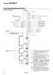
PE LECSS2-T𡱖 LECSS2-T𡱖 CN3 CN8 Note 4) Note 9) CN3 10 m or less 10 m or less Note 4) Note 1) Note 6) Note 7) Note 7) Note 6) Note 7) Note 6) Note 7) 13 9 4 11 MBR DICOM Forced stop 2 Short-circuit connector (Provided as an accessory) FLS RLS DOG 10 D0COM 3 EM2 20 DI1 2 DI2 12 DI3 19 INP 15 ALM 6 LA 16 LAR 7 LB 17 LBR 8 LZ MO1 1 LG 14 MO2 Plate SD LG 18 LZR Electromagnetic brake interlock In position Failure Note 3) A-phase pulse encoder (Differential line driver) SSCNET#optical cable Note 5) (Option) SSCNET# optical cable Note 5) (Option) Cap Note 8) Servo system controller B-phase pulse encoder (Differential line driver) Z-phase pulse encoder (Differential line driver) Control common Analog monitor 1 ±10 VDC ±10 VDC Analog monitor 2 SW1 SW2 (Axis 2) 1 2 3 4 1 2 3 4 1 2 3 4 1 2 3 4 SW1 SW2 RA2 RA3 2 m or less CN1A CN1B CN1A CN1B CN1A CN1B CN1A CN1B RA1 LECSS2-T𡱖 (Axis 3) SW1 SW2 LECSS2-T𡱖 (Axis n) SW1 SW2 Main circuit power supply Note 10) 24 VDC Note 2) 5 DICOM Control Signal Wiring Example: LECSS2-T𡱖 Note 1) For preventing electric shock, be sure to connect the driver , s protective earth (PE) terminal (marked ) to the control panel , s protective earth (PE). Note 2) For interface use, supply 24 VDC ±10% using an external source. Note 3) The failure (ALM) is ON during normal conditions. When it is OFF (alarm occurs), stop the master PLC signal using the master PLC program. Note 4) The same name signals are connected inside the driver. Note 5) Use the following SSCNET# optical cables. Refer to “SSCNET#optical cable” on page 24 for cable models. Cable Cable model Cable length SSCNET# optical cable LE-CSS-𡱖 0.15 m to 3 m Note 6) Connections from Axis 2 onward are omitted. Note 7) Up to 64 axes can be set for the axis selection rotary switch (SW1) and auxiliary axis number setting switches (SW2-3, SW2-4) in combination. Note that the number of connection axes depends on the specifications of the master PLC. Note 8) Be sure to place a cap on unused CN1A/CN1B. Note 9) When not using the STO function, use the driver with the short-circuit connector (provided as an accessory) inserted. Note 10) Configure a circuit to turn off EM2 when the main circuit power is turned off to prevent an unexpected restart of the driver. For sink I/O interface 23 Series LECSS-T