13-e611-lecss2 15 / 31
10秒後にBOOKのページに移動します
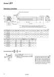
C1 L2 H1 MM L1 Width across flats B1 L oD B + Stroke A + Stroke W Encoder Z-phase detecting position Note 1) Rod operating range (Stroke + G mm) J T EV S EH M K Note 2) M 4 x O1 thread depth R H thread depth C Z V U F±1 [mm] End male thread: LEY ll -llM 25 32 63 ABC * Refer to the WEB catalog for details about the rod end nut and mounting bracket. Note) Refer to the “Mounting” precautions on the WEB catalog when mounting end brackets such as knuckle joint or workpieces. [mm] Size Stroke range (mm) C D EH EV F G H J K L M O1 R S 25 15 to 100 13 20 44 45.5 2 4 M8 x 1.25 24 17 14.5 34 M5 x 0.8 8 45 105 to 400 32 20 to 100 13 25 51 56.5 2 4 M8 x 1.25 31 22 18.5 40 M6 x 1.0 10 60 105 to 500 63 Up to 200 205 to 500 21 40 76 82 4 8 M16 x 2 44 36 37.4 60 M8 x 1.25 16 78 505 to 800 Size Stroke range (mm) T U B V Without lock With lock A W Z A W Z 25 15 to 100 46.5 1.5 136.5 40 233.4 82.4 14.6 274 123 16.3 105 to 400 161.5 258.4 299 32 20 to 100 61 1 156 60 251.1 76.6 17.1 287.9 113.4 17.1 105 to 500 186 281.1 317.9 63 Up to 200 83 5 190.7 60 326.4 98.3 8.1 363.2 205 to 500 225.7 361.4 398.2 135.1 8.1 505 to 800 260.7 396.4 433.2 Size B1 C1 H1 L1* L2 MM 25 22 20.5 8 38 23.5 M14 x 1.5 32 22 20.5 8 42.0 23.5 M14 x 1.5 63 27 26 11 76.4 39 M18 x 1.5 * The L1 measurement is when the unit is in the Z-phase first detecting position. At this position, 2 mm at the end (size 25, 32) and 4 mm at the end (size 63). Dimensions: In-line Motor Note 1) Range within which the rod can move. Make sure a workpiece mounted on the rod does not interfere with the workpieces and facilities around the rod. Note 2) The direction of rod end width across flats (lK) differs depending on the products. 13 Series LEY