12-e595-motorless 61 / 81
10秒後にBOOKのページに移動します
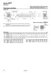
Dimensions: In-line Motor Note 1) Do not allow collisions at either end of the rod operating range at a speed exceeding “pushing speed”. Additionally, when running the positioning operation, do not set within 2 mm of both ends. Note 2) The direction of rod end width across flats (K) differs depending on the products. Without motor flange: LEY DNN LEY25, 32 Dimensions oFD depth FE Motor flange Motor L B + Stroke FF Rod operating range Note 1) H (Stroke + 4 mm) thread depth C M S EH M K Note 2) 4 x O1 thread depth R T EV J 2 x PA thread depth PB PC PC oPG oPE PD PF oFC 2 x FA thread depth FB U oD 13 13 Size 25 32 Size 25 32 20 25 44 51 45.5 56.5 M8 x 1.25 M8 x 1.25 24 31 17 22 12.5 16.5 34 40 M5 x 0.8 M6 x 1.0 8 10 45 60 46.5 61 1.5 1 Stroke range (mm) 15 to 100 105 to 400 20 to 100 105 to 500 Motor type NZ NZ NY [mm] C 89.5 114.5 96 126 B M4 x 0.7 M5 x 0.8 M4 x 0.7 FA 7.5 8.5 8 FB 46 70 70 FC 30 50 50 FD 3.7 3.3 3.3 FE 47 60 60 FF Size 25 32 Motor type NN NN M4 x 0.7 M6 x 1.0 PA 6.5 10 PB 33 40 PC 8 10.5 PD 39 48 PE 15.5 18.5 PF 22 30 PG D EH EV H J K L M O1 R S T U 25 32 . The L measurement is when the unit is at the retracted stroke end position. Series LEY Size 25, 32 Refer to “Motor Mounting” on page 74 for details about motor mounting and included parts. 59