12-e595-motorless 59 / 81
10秒後にBOOKのページに移動します
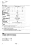
Specifications Weight Model 40 19 156 to 521 1000 800 600 500 20 70 38 304 to 1012 500 400 300 250 30 or less 5000 ±0.02 o20 10 Stroke + 147 50/20 Ball screw Sliding bushing (Piston rod) 5 to 40 90 or less (No condensation) 60 AC servo motor 400 1.27 3000 80 72 573 to 1910 250 200 150 125 5 100, 200, 300, 400, 500, 600, 700, 800 LEY63DN. (In-line) Pushing speed [mm/s] Note 5) Max. acceleration/deceleration [mm/s2] Positioning repeatability [mm] Impact/Vibration resistance [m/s2] Note 6) Actuation type Guide type Operating temperature range [°C] Operating humidity range [%RH] Motor shape Motor type Rated output capacity [W] Rated torque [N・m] Rated rotation [rpm] Stroke [mm] Note 1) Work load [kg] Horizontal Note 2) Vertical Stroke range Up to 500 505 to 600 605 to 700 705 to 800 Series LEY63DN. (Motor mounting position: In-line) Stroke [mm] 100 200 300 400 500 600 700 800 4.2 5.3 7.0 8.2 9.3 11.0 12.1 13.3 Pushing force [N] Note 3) (Set value: Rated torque 30 to 150%) Max. Note 4) speed [mm/s] Product Weight Size 63 Rod end male thread Rod flange (including mounting bolt) Male thread Nut 0.12 0.04 0.51 Additional Weight [kg] Note 1) Consult with SMC for the manufacture of strokes other than shown above. Note 2) The maximum value of the horizontal work load. An external guide is necessary to support the load. The actual work load changes according to the condition of the external guide. Please confirm using actual device. Note 3) The force setting range for the pushing operation (Speed control mode, Torque control mode). The pushing force changes according to the set value. Set it with reference to “Force Conversion Graph” on page 53. Note 4) The allowable speed changes according to the stroke. Note 5) The allowable collision speed for the pushing operation. Note 6) Impact resistance: No malfunction occurred when the actuator was tested with a drop tester in both an axial direction and a perpendicular direction to the lead screw. (Test was performed with the actuator in the initial state.) Vibration resistance: No malfunction occurred in a test ranging between 45 to 2000 Hz. Test was performed in both an axial direction and a perpendicular direction to the lead screw. (Test was performed with the actuator in the initial state.) Note 7) Each value is a guide. Use such value to select a motor capacity. Thread size [mm] Lead [mm] Shaft length [mm] Actuation unit weight [kg] (. [ST]: Stroke) Other inertia [kg・cm2] Mechanical efficiency 0.84 + (2.77 x 10.3) x [ST]: 200 st or less 0.94 + (2.77 x 10.3) x [ST]: Over 200 st, 500 st or less 1.03 + (2.77 x 10.3) x [ST]: Over 500 st 0.056 0.8 Product weight [kg] Series LEY Applicable motor Actuator specifications specifications Other specifications Note 7) Size 63 Ball screw specifications 57