12-e595-motorless@@@58 / 81
10bÐèBOOKäy[WèÖÛçÉñ
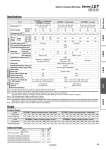
Specifications Weight Model 18 8 65 to 131 900 600 . 12 30 9 79 to 157 1200 800 16 (20) 60 19 154 to 308 600 400 5000 }0.02 50/20 Sliding bushing (Piston rod) 5 to 40 90 or less (No condensation) AC servo motor 3000 60 37 294 to 588 300 200 4 (5) 8 (10) 30 12 98 to 197 1000 640 16 30 or less o12 Stroke + 104.5 ÞÙ60 200 0.64 60 24 192 to 385 500 320 8 60 46 368 to 736 250 160 4 50 16 127 to 255 450 300 . 35 or less o10 6 Stroke + 93.5 ÞÙ40 100 0.32 Ball screw + Belt (LEYÞÙ) Ball screw (LEYÞÙD) Ball screw + Belt [Pulley ratio 1.25:1] Ball screw 50 30 242 to 485 225 150 . 3 30, 50, 100, 150, 200, 250 300, 350, 400 30, 50, 100, 150, 200, 250 300, 350, 400, 450, 500 30, 50, 100, 150, 200, 250 300, 350, 400, 450, 500 LEY25N.ÞÙ (Top/Parallel) LEY25DN.ÞÙ (In-line) LEY32N.ÞÙ (Top/Parallel) LEY32DN.ÞÙ (In-line) Pushing speed [mm/s] Note 5) Max. acceleration/deceleration [mm/s2] Positioning repeatability [mm] Impact/Vibration resistance [m/s2] Note 6) Actuation type Guide type Operating temperature range [C] Operating humidity range [%RH] Motor shape Motor type Rated output capacity [W] Rated torque [NEm] Rated rotation [rpm] Stroke [mm] Note 1) Work load [kg] Horizontal Note 2) Vertical Stroke range Up to 300 305 to 400 405 to 500 Thread size [mm] Lead [mm] (including pulley ratio) Shaft length [mm] Actuation unit weight [kg] (. [ST]: Stroke) Other inertia [kgEcm2] Mechanical efficiency 0.15 + (0.69 x 10.3) x [ST]: 100 st or less 0.16 + (0.69 x 10.3) x [ST]: Over 100 st 0.24 + (1.40 x 10.3) x [ST]: 100 st or less 0.28 + (1.40 x 10.3) x [ST]: Over 100 st 0.012 (LEYÞÙ) 0.015 (LEYÞÙD) 0.035 (LEYÞÙ) 0.061 (LEYÞÙD) 0.8 Series LEY25N.ÞÙ (Motor mounting position: Top/Parallel) LEY32N.ÞÙ (Motor mounting position: Top/Parallel) Stroke [mm] 30 50 100 150 200 250 300 350 400 30 50 100 150 200 250 300 350 400 450 500 0.81 0.88 1.05 1.31 1.49 1.66 1.84 2.01 2.19 1.42 1.53 1.82 2.29 2.57 2.85 3.14 3.42 3.70 3.98 4.26 Series LEY25DN.ÞÙ (Motor mounting position: In-line) LEY32DN.ÞÙ (Motor mounting position: In-line) Stroke [mm] 30 50 100 150 200 250 300 350 400 30 50 100 150 200 250 300 350 400 450 500 0.84 0.91 1.08 1.34 1.52 1.69 1.87 2.04 2.22 1.44 1.55 1.84 2.31 2.59 2.87 3.16 3.44 3.72 4.00 4.28 Pushing force [N] Note 3) (Set value: Rated torque 30 to 90%) Max. Note 4) speed [mm/s] Product Weight Size 25 32 Rod end male thread Foot (2 sets including mounting bolt) Rod flange (including mounting bolt) Head flange (including mounting bolt) Double clevis (including pin, retaining ring and mounting bolt) Male thread Nut 0.03 0.02 0.08 0.17 0.16 0.03 0.02 0.14 0.20 0.22 Additional Weight [kg] Note 1) Consult with SMC for the manufacture of strokes other than shown above. Note 2) The maximum value of the horizontal work load. An external guide is necessary to support the load. The actual work load changes according to the condition of the external guide. Please confirm using actual device. Note 3) The force setting range for the pushing operation (Speed control mode, Torque control mode). The pushing force changes according to the set value. Set it with reference to gForce Conversion Graphh on page 53. Note 4) The allowable speed changes according to the stroke. Note 5) The allowable collision speed for the pushing operation. Note 6) Impact resistance: No malfunction occurred when the actuator was tested with a drop tester in both an axial direction and a perpendicular direction to the lead screw. (Test was performed with the actuator in the initial state.) Vibration resistance: No malfunction occurred in a test ranging between 45 to 2000 Hz. Test was performed in both an axial direction and a perpendicular direction to the lead screw. (Test was performed with the actuator in the initial state.) Note 7) Each value is a guide. Use such value to select a motor capacity. Product weight [kg] Product weight [kg] Electric Actuator/Rod Type Series LEY Size 25, 32 Applicable motor Actuator specifications specifications Other specifications Note 7) Ball screw specifications 56 LEYG LEY LEJS LEFB LEFS Model Selection