12-e595-motorless 55 / 81
10秒後にBOOKのページに移動します
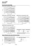
Ratio to rated torque [%] Force [N] Ratio to rated torque [%] Force [N] Ratio to rated torque [%] Force [N] 500 400 300 200 100 0 30 60 90 120 800 700 600 500 400 300 200 100 0 30 60 90 120 600 500 400 300 200 100 0 30 60 90 120 Lead 3: LEY25C Lead 5: LEY32C Lead 10: LEY32B Lead 20: LEY32A Lead 6: LEY25B Lead 12: LEY25A Lead 4: LEY32DC Lead 8: LEY32DB Lead 16: LEY32DA Duty ratio [%] 100 100 (60) 50 (30) 30 (20) Continuous pushing time [minute] . . (1.5) 1.5 (0.5) 0.5 (0.16) Ratio to rated torque [%] 75 or less 90 120 150 .1 The values in ( ) are for a closely-mounted driver. .2 When using the force control or speed control, set the maximum value to be no more than 150% of the rated torque. 0 200 400 600 800 1000 1200 1400 1600 1800 2000 30 60 90 120 150 180 Ratio to rated torque [%] Force [N] Lead 5: LEY63C Lead 10: LEY63B Lead 20: LEY63A LEY63 (Motor mounting position: In-line) 1 10 100 Stroke [mm] Load: F [ N] LEY63 LEY32 LEY25 0 100 200 300 400 500 600 700 800 900 1000 Force Conversion Graph (Guide) LEY25 (Motor mounting position: Top/Parallel, In-line) LEY32 (Motor mounting position: Top/Parallel) LEY32D (Motor mounting position: In-line) . When using the force control or speed control, set the maximum value to be no more than 90% of the rated torque. Graph of Allowable Lateral Load on the Rod End (Guide) F Center of gravity [Stroke] = [Product stroke] + [Distance from the rod end to the center of gravity of the workpiece] Workpiece 53 Size 25, 32, 63 Series LEY