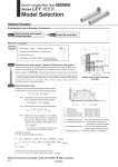
T1 a1 a2 L Speed: V [mm/s] Time [s] T2 T3 T4 0 10 16 20 30 40 0 200 600 1000 1200 Speed [mm/s] Work load [kg] Lead 12: LEY25рӯA Lead 6: LEY25рӯB Lead 3: LEY25рӯC Check the work load.speed. Check the cycle time. рҗWork load: 16 [kg] рҗSpeed: 300 [mm/s] рҗAcceleration/Deceleration: 5,000 [mm/s2] рҗStroke: 300 [mm] рҗWorkpiece mounting condition: Vertical upward downward transfer Calculate the cycle time using the following calculation method. !Cycle time T can be found from the following equation. Select a model based on the workpiece mass and speed which are within the range of the actuator body specifications with reference to the on page 51. Selection example) The LEY25рӯB is temporarily selected based on the graph shown on the right side. T4 = 0.05 [s] !T4: Settling time varies depending on the conditions such as motor types, load and in positioning of the step data. Therefore, please calculate the settling time with reference to the following value. !T2: Constant speed time can be found from the following equation. !T1: Acceleration time and T3: Deceleration time can be obtained by the following equation. W . It is necessary to mount a guide outside the actuator when used for horizontal transfer. When selecting the target model, refer to pages 56 and 57 for the horizontal work load in the specifications, and page 77 for the precautions. The regeneration option may be necessary. Refer to Electric Actuators catalog (CAT.E102) for ҒgRequired Conditions for Regeneration OptionҒh. . The conditions for the settling time vary depending on the AC servo motor or driver to be used. (LEY25рӯ) Electric Actuator/Rod Type Series LEY Model Selection Size 25, 32 Motorless Type Step 1 Step 2 Operating conditions Selection Procedure Positioning Control Selection Procedure Selection Example Step 1 Check the work load.speed. (Vertical transfer) Step 2 Check the cycle time. T = T1 + T2 + T3 + T4 [s] T1 = V/a1 [s] T3 = V/a2 [s] T2 = [s] L . 0.5 ҒE V ҒE (T1 + T3) V L : Stroke [mm] .................. (Operating condition) V : Speed [mm/s] ............... (Operating condition) a1: Acceleration [mm/s2] ... (Operating condition) a2: Deceleration [mm/s2] ... (Operating condition) T1: Acceleration time [s] ... Time until reaching the set speed T2: Constant speed time [s] ... Time while the actuator is operating at a constant speed T3: Deceleration time [s] ... Time from the beginning of the constant speed operation to stop T4: Settling time [s] ... Time until in position is completed Calculation example) T1 to T4 can be calculated as follows. T1 = V/a1 = 300/5000 = 0.06 [s], T3 = V/a2 = 300/5000 = 0.06 [s] T4 = 0.05 [s] Therefore, the cycle time can be obtained as follows. T = T1 + T2 + T3 + T4 = 0.06 + 0.94 + 0.06 + 0.05 = 1.11 [s] T2 = = = 0.94 [s] L . 0.5 ҒE V ҒE (T1 + T3) V 300 . 0.5 ҒE 300 ҒE (0.06 + 0.06) 300 Based on the above calculation result, the LEY25рӯB-300 is selected. 49