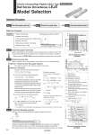
Work load [kg] Speed [mm/s] Overhang: L1 [mm] T1 a1 a2 L Speed: V [mm/s] Time [s] T2 T6 T3 T4 T5 0 20 40 60 80 90 LEJS63B LEJS63A 0 200 400 600 800 1000 1200 L1 Mep m 0 200 100 400 600 800 1,000 0 10 20 30 40 50 60 70 80 Work load [kg] 5000 mm/s2 10000 mm/s2 15000 mm/s2 20000 mm/s2 Selection Procedure Selection Example Step 1 Check the speed.work load. Step 2 Check the cycle time. Step 3 Check the allowable moment. 100 W !Work load: 60 [kg] !Speed: 300 [mm/s] !Acceleration/Deceleration: 3000 [mm/s2] !Stroke: 300 [mm] !Mounting orientation: Horizontal !External force: 10 [N] !Workpiece mounting condition: Operating conditions (LEJS63) (LEJS63) Step 1 Check the speed.work load. Select a model based on the workpiece mass and speed which are within the range of the actuator body specifications with reference to the on page 34. Selection example) The LEJS63B-300 is temporarily selected based on the graph shown on the right side. Step 2 Check the cycle time. Method 2: Calculation Refer to method 1 for a rough estimate, and method 2 for a more precise value. Cycle time T can be found from the following equation. Method 1: Check the cycle time graph (Page 35) The graph is based on the maximum speed of each size. T = T1 + T2 + T3 + T4 [s] T4 = 0.05 [s] T1 = V/a1 [s] T3 = V/a2 [s] T2 = [s] L . 0.5 ・ V ・ (T1 + T3) V !T4 varies depending on the motor type and load. The value below is recommended. !T2 can be found from the following equation. !T1 and T3 can be obtained by the following equation. The acceleration and deceleration values have upper limits depending on the workpiece mass and the duty ratio. Check that they do not exceed the upper limit, by referring to “Work load.Acceleration/Deceleration Graph (Guide)” (Pages 36 and 37). For the ball screw type, there is an upper limit of the speed depending on the stroke. Check that if it does not exceed the upper limit, by referring to the specifications (Page 42). Step 3 Check the allowable moment. L : Stroke [mm] V : Speed [mm/s] a1: Acceleration [mm/s2] a2: Deceleration [mm/s2] Duty ratio: Ratio of T to T6 T ÷ T6 x 100 T1: Acceleration time [s] Time until reaching the set speed T2: Constant speed time [s] Time while the actuator is operating at a constant speed T3: Deceleration time [s] Time from the beginning of the constant speed operation to stop T4: Settling time [s] Time until in position is completed T5: Resting time [s] Time the product is not running T6: Total time [s] Total time from T1 to T5 Calculation example) T1 to T4 can be calculated as follows. T1 = V/a1 = 300/3000 = 0.1 [s], T3 = V/a2 = 300/3000 = 0.1 [s] T4 = 0.05[s] Therefore, the cycle time can be obtained as follows. T = T1 + T2 + T3 + T4 = 0.1 + 0.90 + 0.1 + 0.05 = 1.15 [s] T2 = = = 0.90 [s] L . 0.5 ・ V ・ (T1 + T3) V 300 . 0.5 ・ 300 ・ (0.1 + 0.1) 300 Electric Actuator/High Rigidity Slider Type Ball Screw Drive/Series LEJS Model Selection Refer to “Dynamic Allowable Moment” graphs (Pages 38 and 39). Selection example) Select the LEJS63B-300 from the graph on the right side. Confirm that the external force is within the allowable external force (20 [N]). (The external force is the resistance due to cable duct, flexible trunking or air tubing.) Motorless Type . The conditions for the settling time vary depending on the AC servo motor or driver to be used. 33