12-e595-motorless 12 / 81
10秒後にBOOKのページに移動します
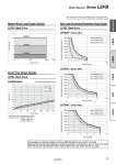
Speed.Work Load Graph (Guide) Work Load.Acceleration/Deceleration Graph (Guide) LEFB/Belt Drive Cycle Time Graph (Guide) LEFB/Belt Drive 0.0 0.5 1.0 1.5 2.0 2.5 3.0 3.5 4.0 4.5 5.0 Cycle time [s] 0 500 1000 1500 2000 2500 3000 Stroke [mm] 5000 10000 20000 Acceleration/Deceleration [mm/s2] LEFB25 (50%) LEFB25 (75%) LEFB25 (100%) LEFB32 (50%) LEFB32 (75%) LEFB32 (100%) LEFB40 (50%) LEFB40 (75%) LEFB40 (100%) 2500 5000 7500 10000 12500 15000 17500 20000 Acceleration/Deceleration [mm/s2] Acceleration/Deceleration [mm/s2] Acceleration/Deceleration [mm/s2] 0 5 10 15 20 Work load [kg] Work load [kg] Work load [kg] 0 5 10 0 2500 5000 7500 10000 12500 15000 17500 20000 0 2500 5000 7500 10000 12500 15000 17500 20000 0 5 10 15 20 25 30 0 LEFB/Belt Drive LEFB32 (Duty ratio) LEFB25 (Duty ratio) LEFB40 (Duty ratio) LEFB25/32/40 . Cycle time is for when maximum speed. . Maximum stroke: LEFB25: 2000 mm LEFB32: 2500 mm LEFB40: 3000 mm 0 1000 2000 2500 Speed [mm/s] 0 5 15 25 30 Work load [kg] LEFB40 LEFB25 LEFB32 . The values shown below are allowable values of the actuator body. Do not use the actuator so that it exceeds these specification ranges. Model Selection Series LEFB These graphs are reference examples of when an SMC standard AC servo motor is mounted. Determine the duty ratio after taking into account the load factor of the AC servo motor or driver to be used. The values show the specifications with a standard SMC motor used. Please use this as a guide. 10 LEYG LEY LEJS LEFB LEFS Model Selection