2-m27-49_en 9 / 34
10秒後にBOOKのページに移動します
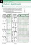
Air Cylinders Model Selection P W W W W W W W W W W W W W W W W W W W W 2 Best Pneumatics 20 25 32 40 20 25 32 40 50 63 80 100 L F G C D U T L F G L F G Mounting style Maximum stroke that can be used according to buckling strength CM2 CG1 Mounting bracket diagram Foot: L Rod side flange: F Head side flange: G Foot: L Rod side flange: F Head side flange: G Foot: L Rod side flange: F Head side flange: G Clevis: C, D Rod side trunnion: U Center trunnion: T Head side trunnion: T Series CA1, CS1 only (cm) 0.3 0.5 0.7 39 29 24 49 37 31 56 42 35 61 46 38 38 29 24 49 36 30 55 42 34 80 60 50 100 76 63 78 59 49 96 73 60 112 85 71 0.3 0.5 0.7 16 11 8 20 14 11 24 17 13 25 17 13 15 11 8 21 14 11 24 17 13 36 26 21 45 33 27 34 25 20 42 31 24 50 37 29 0.3 0.5 0.7 36 26 21 46 34 28 53 39 32 56 42 34 37 27 22 47 35 28 53 40 32 78 59 48 98 74 61 76 57 46 94 70 58 109 82 68 0.3 0.5 0.7 82 62 52 103 79 66 116 89 75 126 97 81 81 61 51 102 78 65 115 88 73 150 126 106 150 159 133 150 124 104 . . . . . . . . . . . . 0.3 0.5 0.7 37 27 22 47 35 29 54 40 33 58 43 35 38 28 23 48 36 30 55 41 34 79 60 50 100 76 63 78 59 48 0.3 0.5 0.7 100 90 76 147 113 95 166 128 107 181 139 117 117 89 75 147 112 94 150 127 107 150 150 150 150 150 150 150 150 150 150 150 150 150 150 150 0.3 0.5 0.7 55 41 34 69 52 43 79 60 49 85 64 53 55 41 34 70 52 43 79 60 50 114 87 72 143 109 91 112 85 71 138 105 87 150 122 102 0.3 0.5 0.7 100 100 100 150 150 136 200 183 154 200 199 167 150 128 108 150 150 135 150 150 150 150 150 150 150 150 150 150 150 150 150 150 150 150 150 150 0.3 0.5 0.7 80 61 50 101 77 64 114 87 72 123 94 78 80 61 50 101 77 64 114 87 73 150 126 105 150 150 132 150 124 103 150 150 127 150 150 148 6 10 16 B L F D B L F B L F Mounting style Maximum stroke that can be used according to buckling strength CJ2 Mounting bracket diagram Foot: L Rod side flange: F Foot: L Rod side flange: F Foot: L Rod side flange: F Clevis: C, D (cm) 0.2 0.3 0.5 0.7 0.2 0.3 0.5 0.7 0.2 0.3 0.5 0.7 0.2 0.3 0.5 0.7 20 20 16 13 . . . . 20 20 20 20 20 20 20 20 29 23 17 14 40 40 32 26 40 40 40 40 40 40 40 40 29 23 17 14 40 40 31 25 40 40 40 40 40 40 40 40 Nominal symbol Operating pressure (MPa) Nominal symbol Operating pressure (MPa) w The relation between the cylinder size and the maximum stroke depending on the mounting style. The aspects indicated below may need to be taken into consideration, depending on how the Step 3 Assuming that the force that is generated by the cylinder itself acts as a buckling force on the piston rod or on the piston rod and the cylinder tube, the table below indicates in centimeters the maximum stroke that can be used, which was obtained through calculation. Therefore, it is possible to find the maximum stroke that can be used with each cylinder size according to the relationship between the level of the operating pressure and the type of cylinder mounting, regardless of the load factor. Reference: Even under a light load, if the piston rod has been stopped by an external stopper at the extending side of the cylinder, the maximum force generated by the cylinder will act upon the cylinder itself. Front matter 34