2-m27-49_en 7 / 34
10秒後にBOOKのページに移動します
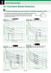
Air Cylinders Model Selection 200 100 50 40 30 20 10 5 4 3 2 1 300 0 500 1000 1500 MB尰100 ・ CA2尰100 MB尰80 ・ CA2尰80 MB尰63 ・ CA2尰63 MB尰50 ・ CA2尰50 MB尰40 ・ CA2尰40 MB尰32 10.00 1.00 0.10 0.01 0 15 30 45 60 75 100 125 150 175 200 250 300 350 400 50 40 30 20 10 5 4 3 2 1 0.5 0.4 0.3 0 100 200 300 400 500 600 700 800 900 1000 CM2尰40 CM2尰32 CM2尰25 CM2尰20 200 100 50 40 30 20 10 54 3 2 1 0.5 0.4 0.3 0.2 0.1 300 0 500 1000 1500 CG1尰100 CG1尰80 CG1尰63 CG1尰50 CG1尰32 CG1尰20 CG1尰25 CG1尰40 CJ2尰10 CJ2尰6 CJ2尰16 2 Best Pneumatics q The maximum stroke at which the cylinder can be operated under a lateral load. The region that does not exceed the bold solid line represents the allowable lateral load in relation to the cylinder of a given stroke length. In the graph, the range of the broken line shows that the long stroke limit has been exceeded. In this region, as a rule, operate the cylinder by providing a guide along the direction of movement. Graph (14) Series MB: o32, o40, o50, o63, o80, o100 Series CA2: o40, o50, o63, o80, o100 Lateral load applied to the rod end fR (N) Cylinder stroke (mm) Graph (11) Series CJ2: o6, o10, o16 Cylinder stroke (mm) Graph (12) Series CM2: o20, o25, o32, o40 Lateral load applied to the rod end fR (N) Cylinder stroke (mm) Graph (13) Series CG1: o20, o25, o32, o40, o50, o63, o80, o100 Cylinder stroke (mm) The aspects indicated below may need to be taken into consideration, depending on how the Step 3 Lateral load applied to the rod end fR (N) Lateral load applied to the rod end fR (N) fR Bushing (Bearing) Front matter 32