2-m27-49_en 3 / 34
10秒後にBOOKのページに移動します
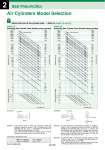
Air Cylinders Model Selection 60000 50000 40000 30000 25000 20000 15000 10000 5000 4000 3000 2500 2000 1500 1000 500 400 300 250 200 150 100 50 40 30 25 20 15 10 5 4 3 2.5 2 1.5 1 0.8 0.8 0.7 0.6 0.5 0.4 0.3 0.2 6000 5000 4000 3000 2500 2000 1500 1000 500 400 300 250 200 150 100 50 40 30 25 20 15 10 5 4 3 2.5 2 1.5 1 0.5 0.4 0.3 0.25 0.2 0.15 0.1 0.08 300 250 200 180 160 140 125 100 80 63 50 40 32 25 20 16 10 6 300 250 200 180 160 140 125 100 80 63 50 40 32 25 20 16 10 6 1 0.7 0.5 0.4 0.3 0.2 60000 50000 40000 30000 25000 20000 15000 10000 5000 4000 3000 2500 2000 1500 1000 500 400 300 250 200 150 100 50 40 30 25 20 15 10 5 4 3 2.5 2 1.5 1 0.8 0.7 0.6 0.5 0.4 0.3 0.2 6000 5000 4000 3000 2500 2000 1500 1000 500 400 300 250 200 150 100 50 40 30 25 20 15 10 5 4 3 2.5 2 1.5 1 0.5 0.4 0.3 0.25 0.2 0.15 0.1 300 250 200 180 160 140 125 100 80 63 50 40 32 25 20 16 10 6 300 250 200 180 160 140 125 100 80 63 50 40 32 25 20 16 10 6 1 0.7 0.5 0.4 0.3 0.2 2 Best Pneumatics Obtain the bore of the cylinder tube. → Refer to Graph (1) and (2). 1 MPa . 10.2 kgf/cm2 1 N . 0.102 kgf 1 kgf/cm2 . 0.098 MPa 1 kgf . 9.8 N Step 1 P = 0 .4 MPa W Fig. (2) 30 kg P = 0.5 MPa Fig. (3) W 100 kg Fig. (1) (Example) P = 0.5 MPa (Example) Bore size (mm) Bore size (mm) Conversion to gravitational units Example 1: If the minimum force of 1000 N is necessary to keep the workpiece pressed as shown in Fig. (1), because this is the extending side, use Graph (1) to determine the load factor of 0.7 and the operating pressure of 0.5 MPa. Then, seek the point at which the cylinder force of 1000 N intersects, and this will result in a bore size of 63 mm. Example 2: To move a load with a 30 kg mass horizontally on a guide as shown in Fig. (2), because the load is the same for both the extending and retracting sides, use Graph (2), which is the retracting side with a smaller force. Determine the load factor of 1, and the operating pressure of 0.4 MPa. Then, seek the point at which it intersects with the load mass of 30 kg, and this will result in a bore size of 40 mm. Example 3: To pull a load with a 100 kg mass vertically upward as shown in Fig. (3), use Graph (2) to determine the load factor of 0.5 and the operating pressure of 0.5 MPa. Then, seek the point at which it intersects with the load mass of 100 kg, and this will result in a bore size of 80 mm. Graph (2) Retracting Side Cylinder Force (Double acting cylinder) Graph (1) Extending Side Cylinder Force (Double acting cylinder) Operating pressure (MPa) Cylinder force F (N) Load mass m (kg) Operating pressure (MPa) Cylinder force F (N) Load mass m (kg) Load factor (η) Load factor (η) Front matter 28