2-m27-49_en 24 / 34
10秒後にBOOKのページに移動します
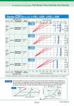
Air Cylinders’ Drive System Full Stroke Time & Stroke End Velocity Series CS1/Bore size: o180, o200, o250, o300 Applicable model Full stroke time (sec) 0.0 1.0 2.0 3.0 4.0 5.0 6.0 7.0 8.0 9.0 10.0 Stroke end velocity (mm/s) 0 50 100 150 200 250 300 350 400 450 500 800 600 400 200 0 Silencer Tubing Speed controller Solenoid valve (2 position) Applicable model Silencer Tubing Speed controller Solenoid valve (2 position) ANB1 -04 AN40 -04 SGP15A AS420 -03 VEX3500-04 VP3145-03 ANB1 -04 AN40 -04 SGP15A AS420 -04 VEX3500-04 VP3145-03 ANB1 -06 AN500 -06 SGP20A AS600 -10 VEX3500-06 VP3145-04 ANB1 -10 AN600 -10 SGP20A AS600 -10 VEX3500-10 VP3145-06 Stroke (mm) 800 600 400 200 0 Stroke (mm) 800 600 400 200 0 Stroke (mm) 800 600 400 200 0 Stroke (mm) o180 o200 o250 o300 10% 30% 50% 70% 10% 30% 70% 50% For details corresponding to each various condition, make the use of “Model Selection Software” on SMC website for your decision. When the cylinder bore size is o, its stroke is L, and load ratio is d%, full stroke time t is obtainted, as an arrow mark q, by reading the value on the abscissa over the point at which the ordinate L hits the full stroke line (red line) of d%. Terminal velocity u is obtained, as an arrow mark w, by reading the value on the abscissa below the point at which the ordinate L hits the terminal velocity line (blue line) of d%. Example o Full stroke time (t ) Stroke end velocity (u) q w d% d% Full stroke time Time (sec) SOL ON OFF Stroke (L) Stroke end velocity Stroke Speed Stroke (mm) Front matter 49