2-m27-49_en 16 / 34
10秒後にBOOKのページに移動します
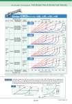
Air Cylinders’ Drive System Full Stroke Time & Stroke End Velocity Series CM2/Bore size: o20, o25, o32, o40 Applicable model Full stroke time (sec) 0.0 0.1 0.2 0.3 0.4 0.5 0.6 0.7 0.8 0.9 1.0 Stroke end velocity (mm/s) 0 100 200 300 400 500 600 700 800 900 1000 200 150 100 50 0 Silencer Tubing Speed controller Solenoid valve (2 position) Applicable model Silencer Tubing Speed controller Solenoid valve (2 position) AN120 -M5 TU0425 AS2201F -01-04 AS2200 -01 SY3120-M5 SYJ5120-M5 VQ1160-M5 AN120 -M5 TU0425 AS2201F -01-04 AS2200 -01 SY3120-M5 SYJ5120-M5 VQ1160-M5 ANB1 -01 AN101 -01 TU0604 AS2201F -01-06 AS2200 -01 SY5120-01 SX5120-01 ANB1 -01 AN101 -01 TU0604 AS2201F -02-06 AS2200 -02 SY5120-01 SX5120-01 Stroke (mm) 200 150 100 50 0 Stroke (mm) 200 150 100 50 0 Stroke (mm) 200 150 100 50 0 Stroke (mm) 10% 30% 50% 70% o20 o25 o32 o40 10% 70% 50% 30% For details corresponding to each various condition, make the use of “Model Selection Software” on SMC website for your decision. When the cylinder bore size is o, its stroke is L, and load ratio is d%, full stroke time t is obtainted, as an arrow mark q, by reading the value on the abscissa over the point at which the ordinate L hits the full stroke line (red line) of d%. Terminal velocity u is obtained, as an arrow mark w, by reading the value on the abscissa below the point at which the ordinate L hits the terminal velocity line (blue line) of d%. Example o Full stroke time (t ) Stroke end velocity (u) q w d% d% Full stroke time Stroke Speed Time (sec) SOL ON OFF Stroke (L) Stroke (mm) Stroke end velocity Front matter 41