309-365-e-leh-en 46 / 59
10秒後にBOOKのページに移動します
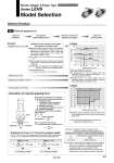
Attachment Workpiece Finger mg μF μF F F Check the gripping force. LEHS20 25 20 15 10 5 0 14 0 20 30 40 60 80 100 LEHS20 傱 Pushing speed is satisfied at the point where 70% of the pushing force and 30 mm/sec of the pushing speed cross. Note) Confirm the pushing speed range from the determined pushing force [%]. 110 100 90 80 70 60 50 40 30 0 10 20 30 40 50 60 Selection Procedure Step Example Guidelines for the selection of the gripper with respect to workpiece mass 傱 Although conditions differ according to the workpiece shape and the coefficient of friction between the attachments and the workpiece, select a model that can provide a gripping force of 7 to 13 times Note) the workpiece weight, or more. Note) For details, refer to the calculation of required gripping force. 傱 If high acceleration or impact forces are encountered during motion, a further margin of safety should be considered. Example) When it is desired to set the gripping force at 13 times or more above the workpiece weight. Required gripping force = 0.1 kg x 13 x 9.8 m/s2 . 12.7 N or more Gripping force F [N] Gripping point L [mm] Pushing force 100% 70% 40% When the LEHS20 is selected. 傱 A gripping force of 14 N is obtained from the intersection point of gripping point distance L = 30 mm and pushing force of 70%. 傱 Gripping force is 14 times greater than the workpiece weight, and therefore satisfies a gripping force setting value of 13 times or more. Gripping point distance: 30 mm Pushing force: 70% Pushing speed: 30 mm/sec Workpiece mass: 0.1 kg Pushing force/Trigger level [%] Pushing speed [mm/sec] Pushing force and trigger level range Calculation of required gripping force When gripping a workpiece as in the figure to the left, and with the following definitions, F : Gripping force (N) μ : Coefficient of friction between the attachments and the workpiece m : Workpiece mass (kg) g : Gravitational acceleration (= 9.8 m/s2) mg : Workpiece weight (N) the conditions under which the workpiece will not drop are 3 x μF > mg and therefore, F > With “a” representing the margin, “F” is determined by the following formula: Number of fingers mg 3 x μ F = x a mg 3 x μ When μ = 0.2 When μ = 0.1 F = x 4 = 6.7 x mg mg 3 x 0.2 F = x 4 = 13.3 x mg mg 3 x 0.1 7 x Workpiece weight 13 x Workpiece weight “Gripping force at least 7 to 13 times the workpiece weight” . The “7 to 13 times or more of the workpiece weight” recommended by SMC is calculated with a margin of “a” = 4, which allows for impacts that occur during normal transportation, etc. . Even in cases where the coefficient of friction is greater than μ = 0.2, for reasons of safety, select a gripping force which is at least 7 to 13 times greater than the workpiece weight, as recommended by SMC. . If high acceleration or impact forces are encountered during motion, a further margin should be considered. Note)