309-365-e-leh-en 21 / 59
10秒後にBOOKのページに移動します
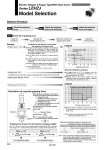
Finger Attachment Workpiece mg μF μF F F Pushing force is one of the values of step data that is input into the controller. Selection Procedure Step 1 Step 1 Check the of gripping force. Check the gripping force. Check the gripping point and overhang. Check the external force on fingers. Pushing force: 70% Gripping point distance: 30 mm LEHZJ20 When the LEHZJ20 is selected. 傱 A gripping force of 27 N is obtained from the intersection point of gripping point distance L = 30 mm and pushing force of 70%. 傱Gripping force is 27.6 times greater than the workpiece weight, and therefore satisfies a gripping force setting value of 20 times or more. Step 2 Step 3 Pushing speed: 30 mm/sec LEHZJ20 傱 Pushing speed is satisfied at the point where 70% of the pushing force and 30 mm/sec of the pushing speed cross. Note) Confirm the pushing speed range from the determined pushing force [%]. Gripping force F [N] Gripping point L [mm] 50 40 30 20 10 0 27 0 20 30 40 60 80 100 120 140 Pushing force 100% 70% 40% Pushing force/Trigger level [%] Pushing speed [mm/sec] 110 100 90 80 70 60 50 40 30 0 10 20 30 40 50 60 Pushing force and trigger level range Electric Gripper 2-Finger Type/With Dust Cover Series LEHZJ Model Selection Step Motor (Servo/24 VDC) Guidelines for the selection of the gripper with respect to workpiece mass 傱 Although conditions differ according to the workpiece shape and the coefficient of friction between the attachments and the workpiece, select a model that can provide a gripping force of 10 to 20 times Note) the workpiece weight, or more. Note) For details, refer to the calculation of required gripping force. 傱 If high acceleration or impact forces are encountered during motion, a further margin of safety should be considered. Example) When it is desired to set the gripping force at 20 times or more above the workpiece weight. Required gripping force = 0.1 kg x 20 x 9.8 m/s2 . 19.6 N or more Workpiece mass: 0.1 kg Example Check the conditions. Select the pushing speed. Calculate the required gripping force. Select the model from gripping force graph. “Gripping force at least 10 to 20 times the workpiece weight” . The “10 to 20 times or more of the workpiece weight” recommended by SMC is calculated with a margin of “a” = 4, which allows for impacts that occur during normal transportation, etc. Calculation of required gripping force