293-307-e-ler-en 6 / 22
10秒後にBOOKのページに移動します
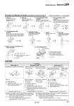
Ι = m1 ・ + m2 ・ 3 a1 2 3 a2 2 Ι = m・ 12 a2 Ι = m・ 12 a2 Ι = m1 ・ 12 4a1 2 + b2 12 4a2 2 + b2 Ι = m・ 12 a2 + b2 Ι = m・ 2 r2 Ι = m・ 5 2r2 Ι = m・ 4 r2 Ι = m1 ・ (Ex.) Refer to 7 when the shape of m2 is spherical. K = m2 ・ + m2 ・a2 2 + K 3 a1 2 5 2r2 1. Find the moment of inertia ΙB for the rotation of shaft (B). 2. Then, replace the moment of inertia ΙB around the shaft (A) by ΙA, b Ι a A = ( )2・ ΙB 1. Thin bar Position of rotation shaft: Perpendicular to a bar through one end 2. Thin bar Position of rotation shaft: Passes through the center of gravity of the bar. 3. Thin rectangular plate (cuboid) Position of rotation shaft: Passes through the center of gravity of a plate. 4. Thin rectangular plate (cuboid) Position of rotation shaft: Perpendicular to the plate and passes through one end. (The same applies to thicker cuboids.) 5. Thin rectangular plate (cuboid) Position of the rotation shaft: Passes through the center of gravity of the plate and perpendicular to the plate. (The same applies to thicker cuboids.) 7. Sphere Position of rotation shaft: Diameter 6. Cylindrical shape (including a thin disk) Position of rotation shaft: Center axis 8. Thin disk (mounted vertically) Position of rotation shaft: Diameter 9. When a load is mounted on the end of the lever 10. Gear transmission Formulas for Moment of Inertia (Calculation of moment of inertia Ι) Ι: Moment of inertia (kg・m2) m: Load mass (kg) L F ω L ω mg μ L mg Load type Static load: Ts Resistance load: Tf Inertial load: Ta Gravity is applied. Friction force is applied. Center of rotation and center of gravity of the load are concentric. Rotation shaft is vertical (up and down). Load Type Only pressing force is necessary. (e.g. for clamping) Necessary torque: T = Ts Gravity or friction force is applied to rotating direction. Necessary torque: T = Tf x 1.5 Note 1) Rotate the load with inertia. Necessary torque: T = Ta x 1.5 Note 1) Note 1) To adjust the speed, margin is necessary for Tf and Ta. Gravity is applied to rotating direction. Tf = m・g・L Friction force is applied to rotating direction. Tf = μ・m・g・L Ts = F・L Ts : Static load (N・m) F : Clamping force (N) L : Distance from the rotation center to the clamping position (m) Tf : Resistance load (N・m) m : Load mass (kg) g : Gravitational acceleration 9.8 (m/s2) L : Distance from the rotation center to the point of application of the gravity or friction force (m) μ : Friction coefficient Ta = Ι・ω ・ ・ 2 π/360 (Ta = Ι・ω ・ ・0.0175) Ta : Inertial load (N・m) Ι : Moment of inertia (kg・m2) ω ・ : Angular acceleration/deceleration (°/sec2) ω : Angular speed (°/sec) . Not resistance load: Neither gravity or friction force is applied to rotating direction. Ex. 1) Rotation shaft is vertical (up and down). Ex. 2) Rotation shaft is horizontal (lateral), and rotation center and the center of gravity of the load are concentric. . Necessary torque is inertial load only. T = Ta x 1.5 . Resistance load: Gravity or friction force is applied to rotating direction. Ex. 1) Rotation shaft is horizontal (lateral), and the rotation center and the center of gravity of the load are not concentric. Ex. 2) Load moves by sliding on the floor. . The total of resistance load and inertial load is the necessary torque. T = (Tf + Ta) x 1.5 a2 m2 m1 a1 r a b r r r a1 a2 b a1 a2 a a (B) (A) Number of teeth = a Number of teeth = b + m2 ・ 307 Model Selection Series LER