293-307-e-ler-enĀ@Ā@Ā@5 / 22
10ēbĆ„ā…BOOKāŐÉyĀ[ÉWā…ąŕďģāĶā‹ā∑
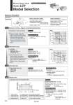
Selection Procedure Electric Rotary Table Series LER Model Selection Step Motor (Servo/24 VDC) q Calculation of moment of inertia q Calculation of cycle time (rotation time) . Angular acceleration time T1 = 420/1,000 = 0.42 sec . Angular deceleration time T3 = 420/1,000 = 0.42 sec . Constant speed time T2 = {180 . 0.5 x 420 x (0.42 + 0.42)}/420 = 0.009 sec . Cycle time T = T1 + T2 + T3 + T4 = 0.42 + 0.009 + 0.42 + 0.2 = 1.049 (sec) w Moment of inertia.Check the angular acceleration/deceleration Select the target model based on the moment of inertia and angular acceleration and deceleration with reference to the (Moment of Inertia .Angular Acceleration/Deceleration graph). T1 É÷ ĀE 1 É÷ ĀE 2 É∆ Speed: É÷ [Āč/sec] Time [s] T2 T3 T4 É∆ : Rotation angle [Āč] É÷ : Angular speed [Āč/sec] É÷ ĀE 1 : Angular acceleration [Āč/sec2] É÷ ĀE 2 : Angular deceleration [Āč/sec2] T1: Acceleration time [s] ĀEĀEĀE Time until reaching the set speed T2: Constant speed time [s] ĀEĀEĀE Time while the actuator is operating at a constant speed T3: Deceleration time [s] ĀEĀEĀE Time from constant speed operation to stop T4: Settling time [s] ĀEĀEĀE Time until in position is completed Angular acceleration time T1 = É÷/É÷ ĀE 1 Angular deceleration time T3 = É÷/É÷ ĀE 2 Constant speed time T2 = {É∆ . 0.5 x É÷ x (T1 + T3)}/É÷ Settling time T4 = 0.2 (sec) Cycle time T = T1 + T2 + T3 + T4 Electric rotary table: LER30J Mounting position: Horizontal Load type: Inertial load Ta Configuration of load: 150 mm x 80 mm (Rectangular plate) Rotation angle É∆: 180Āč Angular acceleration/ angular deceleration É÷ ĀE : 1,000Āč/sec2 Angular speed É÷: 420Āč/sec Load mass (m): 2.0 kg Distance between shaft and center of gravity H: 40 mm Operating conditions Step1 Moment of inertia.Angular acceleration/deceleration Step2 Necessary torque Step3 Allowable load Step4 Rotation time w Check the effective torque Confirm whether it is possible to control the speed based on the effective torque corresponding with the angular speed with reference to the (Effective Torque.Angular Speed graph). q Load type . Static load: Ts . Resistance load: Tf . Inertial load: Ta Effective torque >. Ts Effective torque >. Tf x 1.5 Effective torque >. Ta x 1.5 Inertial load: Ta Ta x 1.5 = Éß x É÷ ĀE x 2 Éő/360 x 1.5 = 0.00802 x 1,000 x 0.0175 x 1.5 = 0.21 NĀEm q Check the allowable load . Radial load . Thrust load . Moment Allowable thrust load >. m x 9.8 Allowable moment >. m x 9.8 x H . Thrust load 2.0 x 9.8 = 19.6 N < Allowable load OK . Allowable moment 2.0 x 9.8 x 0.04 = 0.784 NĀEm < Allowable moment OK Éß = m x (a2 + b2)/12 + m x H2 Éß = 2.0 x (0.152 + 0.082)/12 + 2.0 x 0.042 = 0.00802 kgĀEm2 LER30 0.000 0.005 0.010 0.015 0.020 0.025 0.030 100 1000 10000 Angular acceleration/deceleration: É÷ ĀE (Āč/s2) Moment of inertia: Éß (kgĀEm2) LERūģ30K High torque LERūģ30J Basic LER30 0.0 0.2 0.4 0.6 0.8 1.0 1.2 1.4 0 100 200 300 400 500 Angular speed: É÷ (Āč/s) Effective torque: T (NĀEm) LERūģ30K High torque LERūģ30J Basic H a b Formula Formula Formula Formula Selection example Selection example Selection example Selection example 306