121-210-e-ley-en 89 / 104
10秒後にBOOKのページに移動します
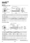
oD oD EV 𡱖V J 𡱖K Note 2) M EH PC 4 x O1 thread depth R M PA oPB Vent hole Note 3) Applicable tubing O.D. o4 H thread depth C A + Stroke B + Stroke Y L S M T Z M U 4 x O1 thread depth R X W Encoder Z phase detecting position Rod operating range Note 1) (Stroke + 4 mm) 2±1 J EV PC T Z S EH M M 𡱖K Note 2) U W 𡱖R A + Stroke B + Stroke Y 4 x O1 thread depth R L H thread depth C Encoder Z phase detecting position Rod operating range Note 1) (Stroke + 4 mm) 2±1 Vent hole Note 3) Applicable tubing O.D. o4 oPBPA Dimensions Motor top mounting type: LEY Note 1) Range within which the rod can move. Make sure a workpiece mounted on the rod does not interfere with the workpieces and facilities around the rod. Note 2) The direction of rod end width across flats (𡱖K) differs depending on the products. Note 3) The vent hole is the port for releasing to atmosphere. Do not apply pressure to this hole. Attach tubing to the vent hole and place the end of the tubing so it is not exposed to dust or water. 15 to 100 101 to 400 20 to 100 101 to 500 Stroke range (mm) Size 25 32 8 10 M5 x 0.8 M6 x 1.0 34 40 14.5 18.5 17 22 24 31 M8 x 1.25 M8 x 1.25 45.5 56.5 44 51 20 25 13 13 116 141 130 160 130.5 155.5 148.5 178.5 R 15.6 15.6 PA 9.3 9.3 PB 40 60 A B C D EH EV H J K L M O1 V 15 to 100 101 to 400 20 to 100 101 to 500 Stroke range (mm) Size 25 32 156.5 156.1 123.5 116.1 115.4 116.6 82.4 76.6 156.9 156.8 123.9 116.8 120 128.2 14.8 15.3 1 1 92 118 46 60 X W X W X W X 15.8 17.1 14.1 17.1 15.8 17.1 14.1 17.1 W Z Z Z Z PC 51 61 Y 87 88.2 Incremental encoder Without lock With lock Absolute encoder S T U Without lock With lock 15 to 100 101 to 400 20 to 100 101 to 500 Stroke range (mm) Size 25 32 M8 x 1.25 M8 x 1.25 45.5 56.5 44 51 20 25 13 13 136.5 161.5 156 186 274.5 299.5 290.6 320.6 123.5 116.1 82.4 76.6 233.4 258.4 251.1 281.1 123.9 116.8 274.9 299.9 291.3 321.3 87 88.2 238 263 262.7 292.7 B C D EH EV H 15 to 100 101 to 400 20 to 100 101 to 500 Stroke range (mm) Size 25 32 15.3 15.3 1.5 1 46.5 61 45 60 40 60 9.3 9.3 8 10 M5 x 0.8 M6 x 1.0 34 40 14.5 18.5 17 22 24 31 PC 71.5 87 R PA PB V S T U Y 15.6 15.6 A W A W Incremental encoder Without lock With lock W A W 16.3 17.1 14.6 17.1 16.3 17.1 14.6 17.1 Z Z A Z Z Absolute encoder Without lock With lock J K L M O1 25 32 For the rod end male thread, refer to page 195. For the mounting bracket dimensions, refer to page 152. In-line motor type: LEY 2 5 D 32 206 Series LEY-X5 Dust/Drip Proof (IP65) Specification