121-210-e-ley-enü@ü@ü@87 / 104
10ĢbīŃé╔BOOKé╠āyü[āWé╔ł┌ō«éĄé▄éĘ
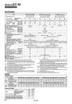
Specifications Weight Size 25 32 Lock Rod end male thread Foot (2 sets including mounting bolt) Rod flange (including mounting bolt) Head flange (including mounting bolt) Incremental encoder Absolute encoder Male thread Nut 0.20 0.30 0.03 0.02 0.08 0.17 0.40 0.66 0.03 0.02 0.14 0.20 Additional Weight [kg] 45 145 2 8 445 65 175 2 8 724 65 175 2 8 724 Model 18 8 65 to 131 900 600 . 12 8 or more 3 or more 131 50 16 127 to 255 450 300 . 35 or less 5,000 6 50/20 Ball screw + Belt/Ball screw Sliding bushing (Piston rod) 5 to 40 90 or less (No condensation) 31 or more 2 or more 100 W/«40 AC servo motor (100/200 VAC) 255 6.3 30, 50, 100, 150, 200 250, 300, 350, 400 30, 50, 100, 150, 200, 250 300, 350, 400, 450, 500 30, 50, 100, 150, 200, 250 300, 350, 400, 450, 500 Motor type S2, S3: Incremental 17-bit encoder (Resolution: 131072 p/rev) Motor type S6, S7: Absolute/incremental dual 18-bit encoder (Resolution: 262144 p/rev) 50 30 242 to 485 225 150 . 3 Not required 2 or more 485 30 9 79 to 157 1200 800 20 Note 7) 15 or more 6 or more 157 60 19 154 to 308 600 400 30 or less ü}0.02 ü}0.01 0.1 or less 0.05 or less 10 Note 7) Ball screw + Belt IP65 Not required 7 or more Non-magnetizing lock 308 7.9 24 VDC 60 37 294 to 588 300 200 5 Note 7) Not required 11 or more 588 30 12 98 to 197 1000 640 16 23 or more 6 or more 197 60 24 192 to 385 500 320 30 or less 8 Ball screw Not required 7 or more 385 7.9 60 46 368 to 736 250 160 4 Not required 12 or more 736 5,000 50/20 Sliding bushing (Piston rod) 5 to 40 90 or less (No condensation) 200 W/«60 AC servo motor (100/200 VAC) Pushing speed [mm/s] Note 5) Max. acceleration/deceleration [mm/s2] Lead [mm] Impact/Vibration resistance [m/s2] Note 8) Actuation type Guide type Enclosure Operating temperature range [üŗC] Operating humidity range [%RH] Motor output/Size Motor type Encoder Max. instantaneous power consumption [W] Note 12) Type Note 13) Holding force [N] Power consumption [W] at 20üŗC Note 14) Rated voltage [V] Positioning repeatability [mm] Lost motion [mm] Note 6) Work load [kg] Pushing force [N] Note 3) (Set value: 15 to 30%) Stroke [mm] Note 1) Horizontal Note 2) Vertical Lock unit Electric specifications Actuator specifications specifications Note 4) Max. speed [mm/s] Required conditions for Note 9) ügRegeneration optionüh [kg] Stroke range Up to 300 305 to 400 405 to 500 Horizontal Vertical Horizontal Vertical Horizontal Vertical Basic type High precision type Basic type High precision type LEY32DS (In-line) 37 LEY32S (Top mounting) 37 LEY25S /LEY25DS 26 26 0 .10% Product Weight [kg] LEY25S« (Motor mounting position: Top mounting) LEY32S« (Motor mounting position: Top mounting) 30 50 100 150 200 250 300 350 400 30 50 100 150 200 250 300 350 400 450 500 LEY25DS« (Motor mounting position: In-line) LEY32DS« (Motor mounting position: In-line) 50 100 150 200 250 300 350 400 30 50 100 150 200 250 300 350 400 450 500 1.31 1.37 1.38 1.44 1.55 1.61 1.81 1.87 1.99 2.05 2.16 2.22 2.34 2.40 2.51 2.57 2.69 2.75 2.42 2.36 2.53 2.47 2.82 2.76 3.29 3.23 3.57 3.51 3.85 3.79 4.14 4.08 4.42 4.36 4.70 4.64 4.98 4.92 5.26 5.20 1.34 1.40 1.41 1.47 1.58 1.64 1.84 1.90 2.02 2.08 2.19 2.25 2.37 2.43 2.54 2.60 2.72 2.78 2.44 2.38 2.55 2.49 2.84 2.78 3.31 3.25 3.59 3.53 3.87 3.81 4.16 4.10 4.44 4.38 4.72 4.66 5.00 4.94 5.28 5.22 Motor type Motor type Series Stroke [mm] Series Incremental encoder Absolute encoder Incremental encoder Absolute encoder Stroke [mm] 30 Power consumption [W] Note 10) Standby power consumption when operating [W] Note 11) Note 1) Consult with SMC for non-standard strokes as they are produced as special orders. Note 2) The maximum value of the horizontal work load. An external guide is necessary to support the load. The actual work load changes according to the condition of the external guide. Please confirm using actual device. Note 3) The force setting range (set values for the driver) for the pushing operation with the torque control mode, etc. Set it with reference to ügForce Conversion Graphüh on page 188. Note 4) The allowable speed changes according to the stroke. Note 5) The allowable collision speed for the pushing operation with the torque control mode, etc. Note 6) A reference value for correcting an error in reciprocal operation. Note 7) Equivalent lead which includes the pulley ratio [1.25:1] Note 8) Impact resistance: No malfunction occurred when the actuator was tested with a drop tester in both an axial direction and a perpendicular direction to the lead screw. (Test was performed with the actuator in the initial state.) Vibration resistance: No malfunction occurred in a test ranging between 45 to 2000 Hz. Test was performed in both an axial direction and a perpendicular direction to the lead screw. (Test was performed with the actuator in the initial state.) Note 9) The work load conditions which require ügRegeneration optionüh when operating at the maximum speed (Duty ratio: 100%). Order the regeneration option separately. For details and order numbers, refer to ügRequired Conditions for Regeneration Optionüh on pages 186 and 187. Note 10) The power consumption (including the driver) is for when the actuator is operating. Note 11) The standby power consumption when operating (including the driver) is for when the actuator is stopped in the set position during the operation. Note 12) The maximum instantaneous power consumption (including the driver) is for when the actuator is operating. Note 13) Only when motor option ügWith locküh is selected. Note 14) For an actuator with lock, add the power consumption for the lock. 204 Series LEY-X5 Dust/Drip Proof (IP65) Specification B