121-210-e-ley-en 83 / 104
10秒後にBOOKのページに移動します
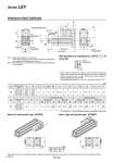
T Z U M S M 4 x O1 A + Stroke thread depth R B + Stroke Y L X W Encoder Z phase detecting position 4±0.1 Rod operating range (Stroke + 8 mm) oD EV 𡱖V J EH M 4 x O1 thread depth R M H x 2 thread depth C 𡱖K Note 2) Note 1) ZZ T2 S1 U S1 T2 U Dimensions: Motor Top/Parallel [mm] Size Stroke range [mm] A B C D EH EV H J K L M O1 R S Y 63 Up to 200 192.6 155.2 205 to 500 227.6 190.2 21 40 76 82 M16 x 2 44 36 37.4 60 M8 x 1.25 16 80 32.2 505 to 800 262.6 225.2 Size Stroke range [mm] T U V Incremental encoder Absolute encoder Without lock With lock Without lock With lock W X Z W X Z W X Z W X Z 63 Up to 200 146 4 60 110.2 150.2 15.6 (16.6)* 138.8 178.8 15.6 (16.6)* 98.5 138.5 15.6 (16.6)* 138 178 15.6 (16.6)* 205 to 500 505 to 800 Note 1) Range within which the rod can move. Make sure a workpiece mounted on the rod does not interfere with the workpieces and facilities around the rod. Note 2) The direction of rod end width across flats (𡱖K) differs depending on the products. Note) When the motor is mounted on the left or right side in parallel, the groove for auto switch on the side to which the motor is mounted is hidden. [mm] Size S1 T2 U 63 84 142 4 Motor left side parallel type: LEY63L Motor right side parallel type: LEY63R * The values in ( ) are the dimensions when L is selected for screw lead. 197-6 Series LEY Rc1/8 Vent hole tap. 18 IP65 (Dust/Drip proof specification): LEY63𡱖𡱖𡱖-𡱖P (View ZZ) * When using the dust/drip proof (IP65), correctly mount the fitting and tubing to the vent hole tap, and then place the end of the tubing in an area not exposed to dust or water. The fitting and tubing should be provided separately by the customer. Select [Applicable tubing O.D.: o4 or more, Connection thread: Rc1/8]. B