121-210-e-ley-enĀ@Ā@Ā@81 / 104
10ēbĆ„ā…BOOKāŐÉyĀ[ÉWā…ąŕďģāĶā‹ā∑
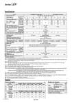
197-4 Series LEY Weights Product Weights [kg] Additional Weights [kg] Specifications Note 1) Consult with SMC for non-standard strokes as they are produced as special orders. Note 2) The maximum value of the horizontal work load. An external guide is necessary to support the load. The actual work load changes according to the condition of the external guide. Please confirm using actual device. Note 3) Set values for the driver. Note 4) The force setting range (set values for the driver) for the pushing operation with the torque control mode etc. The pushing force and duty ratio change according to the set value. Set it with reference to ĀgForce Conversion GraphĀh on page 197-2. Note 5) The allowable speed changes according to the stroke. Note 6) The allowable collision speed for the pushing operation with the torque control mode etc. Note 7) A reference value for correcting an error in reciprocal operation. Note 8) Impact resistance: No malfunction occurred when the actuator was tested with a drop tester in both an axial direction and a perpendicular direction to the lead screw. (Test was performed with the actuator in the initial state.) Vibration resistance: No malfunction occurred in a test ranging between 45 to 2000 Hz. Test was performed in both an axial direction and a perpendicular direction to the lead screw. (Test was performed with the actuator in the initial state.) Note 9) The work load conditions which require ĀgRegeneration optionĀh when operating at the maximum speed (Duty ratio: 100%). Note 10) The power consumption (including the driver) is for when the actuator is operating. Note 11) The standby power consumption when operating (including the driver) is for when the actuator is stopped in the set position during the operation. Note 12) The maximum instantaneous power consumption (including the driver) is for when the actuator is operating. Note 13) Only when motor option ĀgWith lockĀh is selected. Note 14) For an actuator with lock, add the power consumption for the lock. Model LEY63S48 ūģ (Top/Parallel) LEY63DS48 ūģ (In-line) Actuator specifications Stroke [mm] Note 1) 100, 200, 300, 400, 500, 600, 700, 800 Work load [kg] Horizontal Note 2) 40 70 80 200 40 70 80 Vertical 19 38 72 115 19 38 72 Pushing force [N]/Set value Note 3) : 15 to 50% Note 4) 156 to 521 304 to 1,012 573 to 1,910 1,003 to 3,343 156 to 521 304 to 1,012 573 to 1,910 Note 5) Max. speed [mm/s] Stroke range Up to 500 1000 500 250 70 1000 500 250 505 to 600 800 400 200 800 400 200 605 to 700 600 300 150 600 300 150 705 to 800 500 250 125 500 250 125 Pushing speed [mm/s] Note 6) 30 or less Max. acceleration/deceleration [mm/s2] 5,000 3,000 5,000 Positioning repeatability [mm] Basic type Ā}0.02 High precision type Ā}0.01 Lost motion [mm] Note 7) Basic type 0.1 or less High precision type 0.05 or less Screw lead [mm] (including pulley ratio) 20 10 5 5 (2.86) 20 10 5 Impact/Vibration resistance [m/s2] Note 8) 50/20 Actuation type Ball screw Ball screw + Belt [Pulley ratio 4:7] Ball screw Guide type Sliding bushing (Piston rod) Operating temperature range [ĀčC] 5 to 40 Operating humidity range [%RH] 90 or less (No condensation) Required conditions for Note 9) ĀgRegeneration optionĀh [kg] Horizontal Not required Not required Not required Not required Not required Not required Not required Vertical 2 or more 5 or more 12 or more 46 or more 2 or more 5 or more 12 or more Electric specifications Motor output/Size 400 W/ūģ60 Motor type AC servo motor (200 VAC) Encoder Motor type S4: Incremental 17-bit encoder (Resolution: 131072 p/rev) Motor type S8: Absolute 18-bit encoder (Resolution: 262144 p/rev) Power consumption [W] Note 10) Horizontal 210 Vertical 230 Standby power consumption when operating [W] Note 11) Horizontal 2 Vertical 18 Max. instantaneous power consumption [W] Note 12) 1275 Lock unit specifications Type Note 13) Non-magnetizing lock Holding force [N] 313 607 1,146 2,006 313 607 1,146 Power consumption [W] at 20ĀčC Note 14) 7.9 Rated voltage [V] 24 VDC 0 .10% Size 63 Lock Incremental encoder 0.4 Absolute encoder 0.6 Rod end male thread Male thread 0.12 Nut 0.04 Foot (2 sets including mounting bolt) 0.26 Rod flange (including mounting bolt) 0.51 Double clevis (including pin, retaining ring and mounting bolt) 0.58 Series LEY63Sūģ (Motor mounting position: Top/Parallel) Stroke [mm] 100 200 300 400 500 600 700 800 Motor type Incremental encoder 5.4 6.6 8.3 9.4 10.5 12.2 13.4 14.5 Absolute encoder 5.5 6.7 8.4 9.5 10.6 12.3 13.5 14.6 Series LEY63DSūģūģ (Motor mounting position: In-line) Stroke [mm] 100 200 300 400 500 600 700 800 Motor type Incremental encoder 5.6 6.7 8.4 9.6 10.7 12.4 13.5 14.7 Absolute encoder 5.7 6.8 8.5 9.7 10.8 12.5 13.6 14.8 B