121-210-e-ley-en 7 / 104
10秒後にBOOKのページに移動します
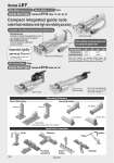
When the cylinder is retracted (initial value), the non-rotating accuracy without a load or deflection of the guide rods will be below the values shown in the table. Bore size (mm) Sliding bearing Ball bushing bearing 16 ±0.06° ±0.07° 25 ±0.05° ±0.06° 32 40 Compact integrated guide rods Lateral load resistance and high non-rotating accuracy Direct Mounting Head end Rod end Body bottom Bracket Mounting Head flange Double clevis . Body bottom tapped: When “U” is selected Application Examples Lifter Delivery Rotation Pushing operation Press fitting Stopper Improved rigidity Lateral end load: 5 times more. . Compared with rod type, size 25 and 100 stroke Non-rotating accuracy improved by using two guide rods Guide Rod Type Series LEYG /Size: 16, 25, 32, 40 Sliding bearing Suitable for lateral load applications such as a stopper where shock is applied Ball bushing bearing Smooth operation suitable for pusher and lifter Compatible with sliding bearing and ball bushing bearing Motor top mounting type In-line motor type Step Motor (Servo/24 VDC) Servo Motor (24 VDC) Type Guide Rod Type Series LEYG /Size: 25, 32 Foot Rod flange Mounting Variations AC Servo Motor Type Guide rod type Guide rod type/ In-line motor type Series LEY For use of auto switches for the guide rod type LEYG series, refer to page 219. 130