121-210-e-ley-en 74 / 104
10秒後にBOOKのページに移動します
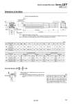
L oD B + Stroke A + Stroke W Encoder Z phase detecting position Rod operating range Note 1) (Stroke + 4 mm) C1 L2 H1 MM L1 Width across flats B1 J T EV S EH M 𡱖K Note 2) M 4 x O1 thread depth R H thread depth C Z 𡱖V U Dimensions: In-line Motor 13 13 Size [mm] 25 32 Note 1) Range within which the rod can move. Make sure a workpiece mounted on the rod does not interfere with the workpieces and facilities around the rod. Note 2) The direction of rod end width across flats (𡱖K) differs depending on the products. C 20 25 D 44 51 EH 45.5 56.5 EV M8 x 1.25 M8 x 1.25 H 24 31 J 17 22 K 14.5 18.5 L 34 40 M M5 x 0.8 M6 x 1.0 O1 8 10 R 45 60 S 46.5 61 T 1.5 1 U Stroke range (mm) 15 to 100 105 to 400 20 to 100 105 to 500 Size 25 32 Stroke range (mm) 15 to 100 105 to 400 20 to 100 105 to 500 136.5 161.5 156 186 B 40 60 V End male thread: LEY 2 5 𡱖𡱖 -𡱖𡱖M 32 ABC . Refer to page 152 for details about the rod end nut and mounting bracket. Note) Refer to the “Handling” precautions on page 220 when mounting end brackets such as knuckle joint or work pieces. 22 22 20.5 20.5 Size 25 32 B1 C1 8 8 H1 38 42.0 L1 23.5 23.5 L2 M14 x 1.5 M14 x 1.5 MM [mm] . The L1 measurement is when the unit is in the original position. At this position, 2 mm at the end. 2±1 Without lock With lock Without lock Incremental encoder Absolute encoder With lock 87 88.2 123.9 116.8 82.4 76.6 123.5 116.1 238 263 262.7 292.7 A W 274.9 299.9 291.3 321.3 A W 233.4 258.4 251.1 281.1 A W 274.5 299.5 290.6 320.6 A W 14.6 17.1 Z 16.3 17.1 Z 14.6 17.1 Z 16.3 17.1 Z 195 Electric Actuator/Rod Type Series LEY Size 25, 32